BubsBuilds Projects

- Details
- Parent Category: System-level Projects
- Category: Project Fireplace
The goal for this build was for a fairly simple electronics enclosure. The "requirements" were:
- Provide space for 'mounting' (just using the adhesive backing) for a medium solderless breadboard
- Interior space must accommodate a USB connection to an Arduino Nano at one end of the breadboard
- At least two mount points to 2020 extrusion (or comparable M5 mount with flexible spacing)
- Integrated strain relief
- A secure form of strain relief with at least two separate 'channels'
- Prefer a 'permanent' option over integrated zip tie attach points, but not required
And here is what I came up with:
 |
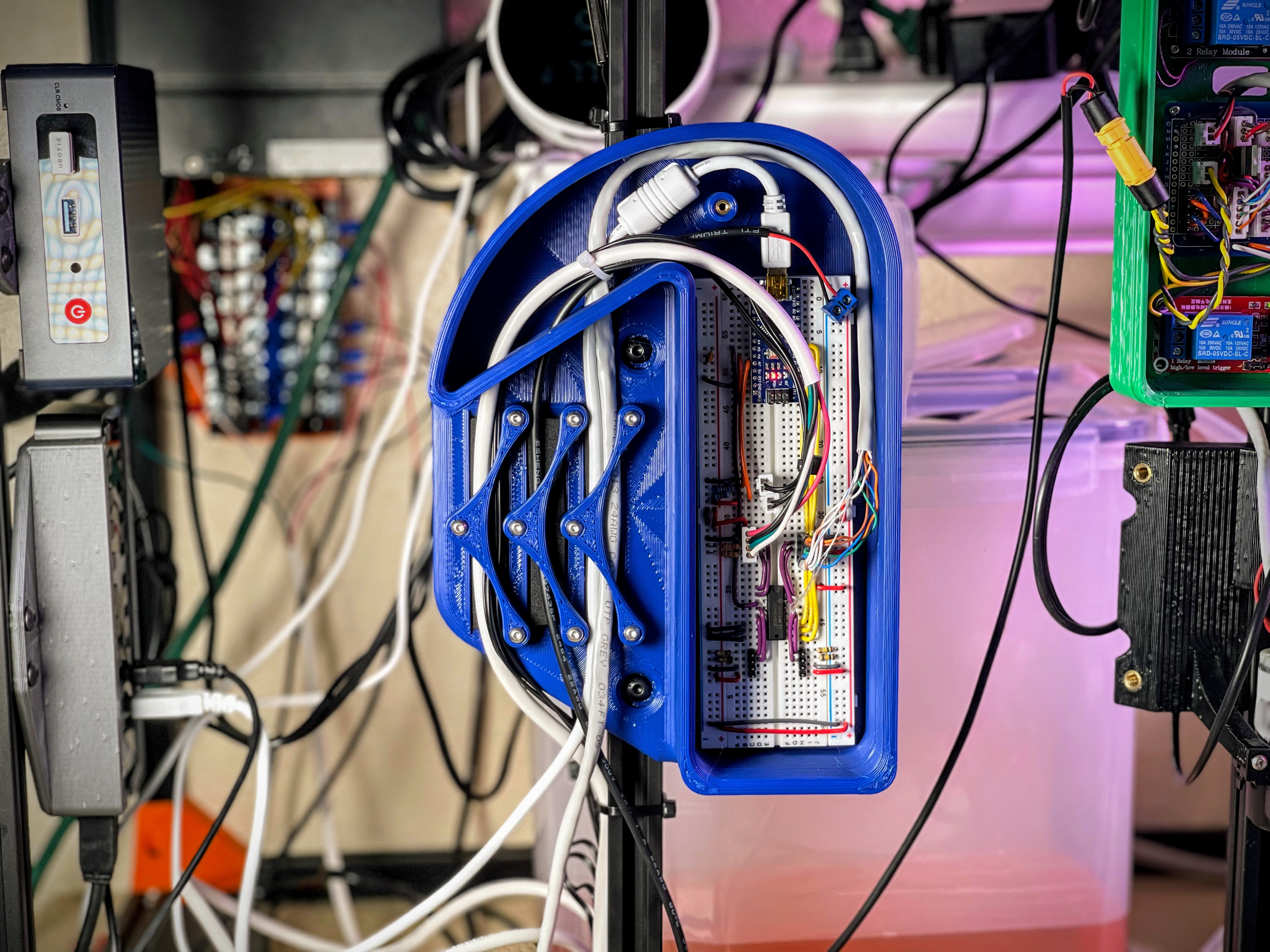 |
There is an enclosed(ish) volume that is spaced on three sides for just a conservative clearance fit, and the fourth side opens up to provide something of a conduit for the cabling. The conduit directs the cables around a 180 degree bend and then out one of three ports.
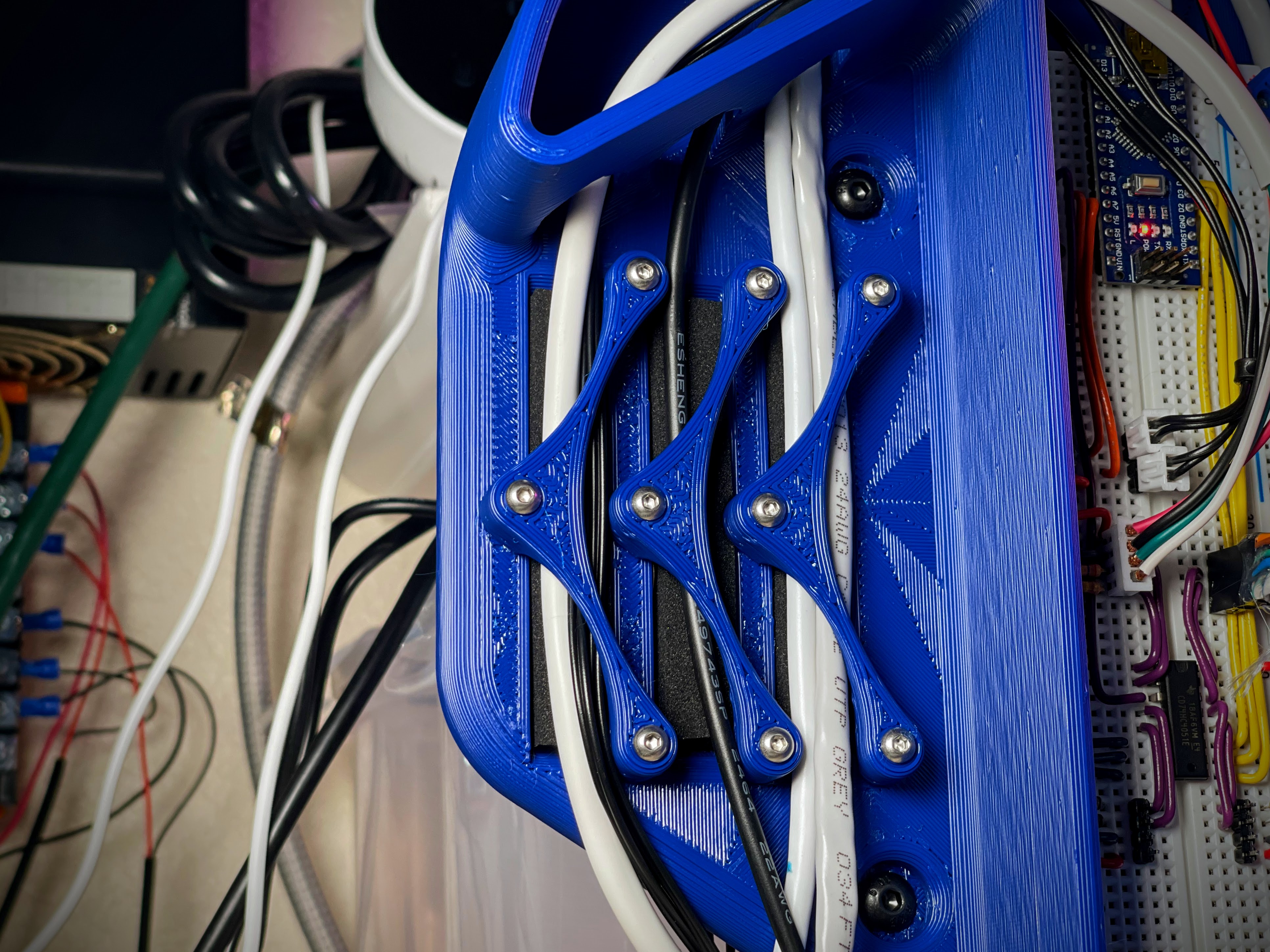
In line with each of the ports are the strain relief elements. Each strain relief hold down is secured with three, M3 fasteners....yeah....quite overkill, but I was sort of locked in on the nested aesthetic they have goin on ¯\_(ツ)_/¯. Under each hold down is a recess intended for a strip of adhesive-backed foam. This allows for a rigid hold down, and firm strain relief, but without over-constraining the cables.
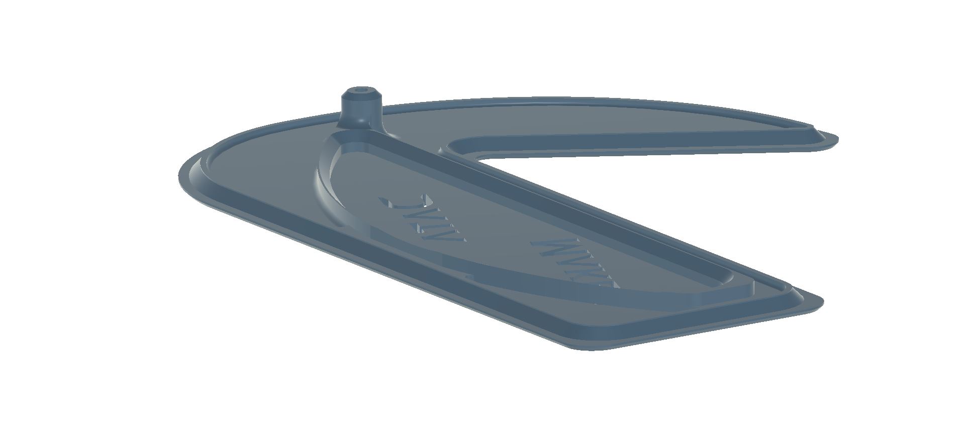
The lid is secured with a single M3...yeah, was overly conservative here, after over-doing it on the strain reliefs. My bad. I added some stiffening supports on the back side of the lid, shown in the image below. It works well enough that I don't have any intentions of revising the assembly to add a second fastener point, but a second attachment point down at the bottom (assuming the orientation shown in the above pictures) would slightly improve the 'fit and finish' for the seams on the bottom side.
Parts List:
- Printed Parts - For the pictured build, I printed all of the below from Blue Overture PETG
- (1) Enclosure.stl
- (1) Lid.stl
- (3) CableHolddown.stl
- COTS
- 1/2"x1/4" Weather stripping foam - Each recess is 75mm (~3") long. So these rolls are definitely more than needed for just this project. But I find having the stuff around to be handy :)
- (9) M3x16 BHCS - The fastener only has to actually extend 10mm (nominally) through the hold down, so shorter fasteners should be fine, but I find that going a bit longer helps keep the wires where I want them as I'm securing the hold down.
- (1) M3x10 BHCS - For holding down the lid. Goes through 5mm of material.
- (10) M3x6 Heat sets - One for each hold down mount point and one for the lid.
If you're interested in the bits inside the box, or if you have any questions, let me know in the comments!
- Details
- Parent Category: BubsBuilds Projects
- Category: Just Playin and Concept Demo Projects
Ummm, yeah...so I'm just gonna upfront admit that this just plain didn't need to exist, and isn't even particularly successful...I mean, it holds paper towels, so I guess it's "successful"...anyway
 |
 |
So the motivation here was that I got frustrated when I pulled a paper towel and got the whole roll, and but five minutes later, I pulled on the toilet paper roll only to be granted one square at a time. Clearly this wrong needed righting through improved dynamics, or somethin. I decided if I could crank up the damping (the velocity-dependent resistance), then the dispenser would basically pull back proportional to how hard I yank the paper, or at least that's the idea.
Key features/phrases to make it sound impressive:
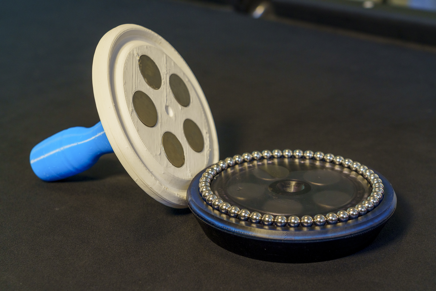
- Base contains a magnetically-coupled fluid damper
- The base itself has an integrated stator and locating features/bearing races for the rotor
- The magnetic coupler between the rotor and the turntable also provides the preload for their respective bearings (and hold the thing together)
- The base is sealed with a printable TPU gasket
- Paper towel is 'secured' to the holder with the compliant, TPU post.
Soooo, I'm not really expecting anyone to do as I've done, and build one of these things, so I'm not currently planning to include a step-by-step build for this. But, if I'm somehow wrong, and you'd some more info, drop me a comment on Printables or the like...and I'll very much consider it :)
But here's a quick overview of the parts:
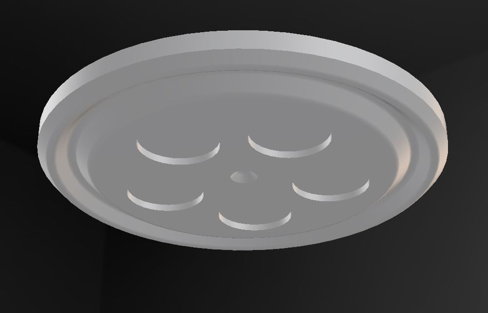
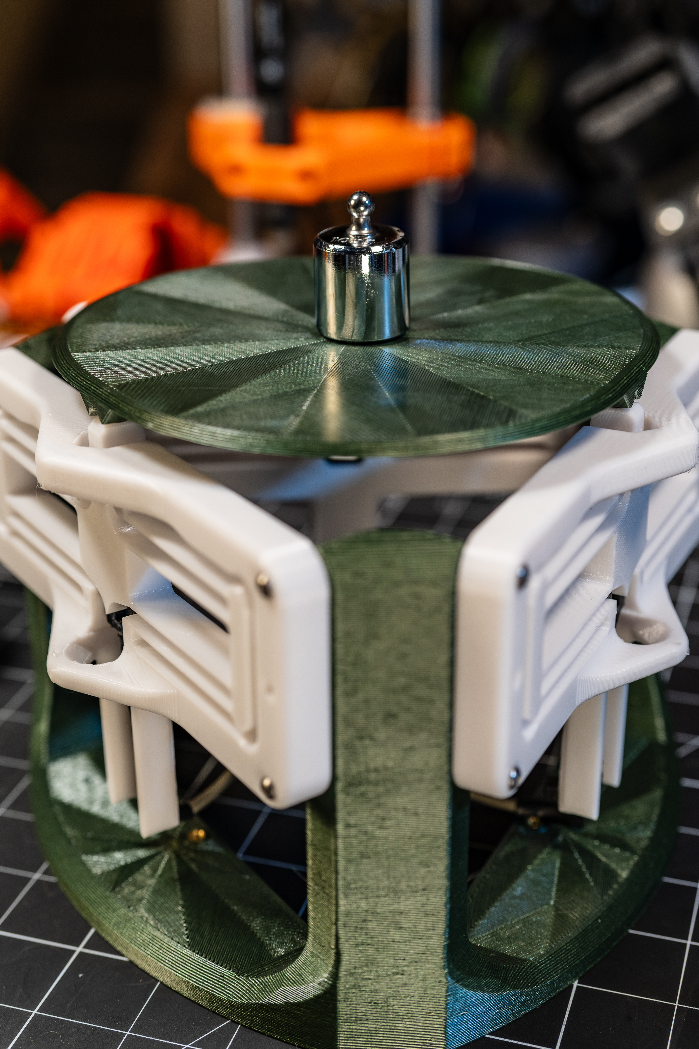
Base/Stator
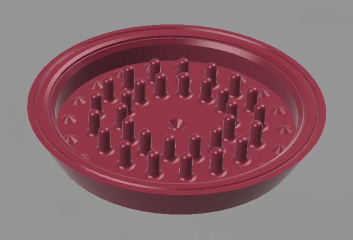
The posts arranged around the middle are there to create additional drag in the working fluid and increase the damping. The grooves around the perimeter are for the gasket and adhesive to seal it up. And the cone cutout in the center is for a "jewel bearing" that locates the rotor and is...get this...a bearing :)
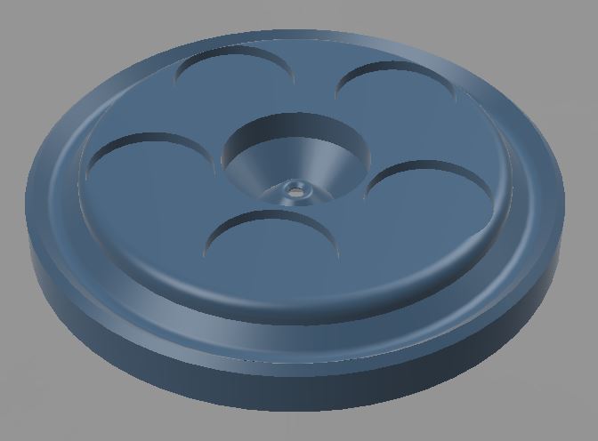
Rotor
 |
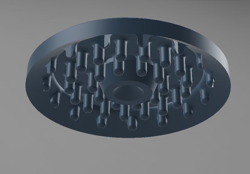 |
The bottom side of the rotor (image on the right) includes the mates for the above-referenced drag posts and jewel bearing. On the top, the five large cylindrical pockets are for the magnets that will do the coupling. And in the center and around the perimeter, more bearing races.
NOTE: on the bearing races on the top of the rotor, this is over-constrained, but I was worried about possible deformation in the rotor due to the magnets, and didn't want to risk the posts colliding. However, I think there is likely sufficient stiffness in the rotor to leave the inner race empty. So you'd only use the one jewel bearing on the bottom (with a single large ball) and the outer ring of 3/8" balls.
Gasket
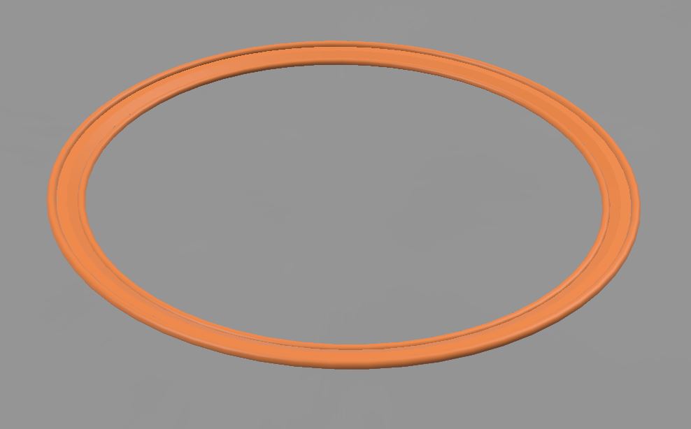
The gasket is not intended as a stand alone seal, as the intent is/was to bond the shell together using a waterproof adhesive (like Goop...actually Goop, I used Goop). So the idea is to print the gasket from TPU, and lay beads of Goop in both of the flat regions. This has seemed to hold up great for mine. It's been about a year since I first built this and it hasn't lost a drop of oil.
Top Plate
 |
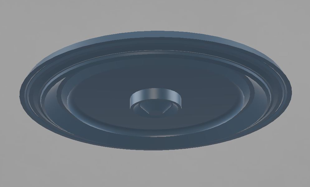 |
The bottom side of the top plate has the mates for the gasket and rotor bearings. As mentioned above, I would recommend only using the outer bearing race here. On the top surface are another jewel bearing cone and a v-groove race. Leave the cone empty, and only use the outer race with 3/8" balls.
Spool Plate
The Spool Plate could probably be printed combined with the Flexure Tube, but I separated them so that I could make the bearing races from a stiffer plastic like PLA. It has pockets for the other half of the coupler magnets, and a v-groove for the bearing on the bottom, and a recess for gluing on the Flexure Tube on top.
Flexure Tube (aka the actual paper towel holding part)
 |
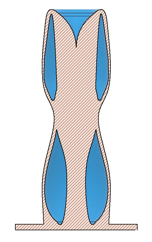 |
Guess it's pretty much been covered already above, but it's a flexi part, intended to be printed in TPU, but i've also made them from PETG (but much less 'flexi', of course).
- Details
- Parent Category: Just Playin and Concept Demo Projects
- Category: Flexure Fun
WIP
Subcategories
Assorted (hopefully) "Useful Stuff" Projects Article Count: 12
Like the bucket of assorted fasteners on that bottom shelf, this category is for stuff that I didn't know how to group...oh, and speaking of those fasteners, check out the little sortin fella!
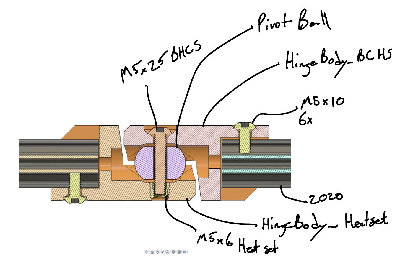
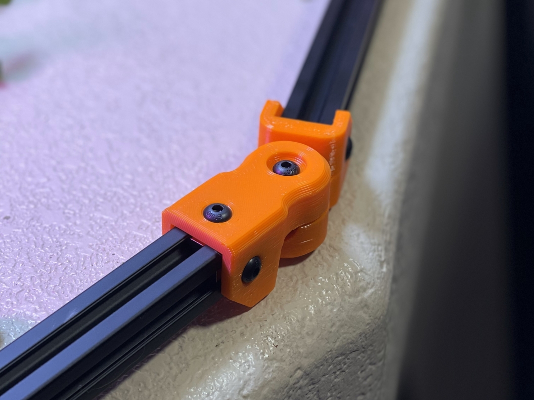
2020 Aluminum Extrusion Hardware
|
Quick Bolt Sorter
|
General Purpose Turntable - Gen1
Games Article Count: 1
Generative Design Projects Article Count: 3
During the good financial decision-making times of Covid lockdowns, etc. I decided it was a good idea to buy a license for the Fusion360 Generative Design extension...Good news, I did finally pay that off :) I had worked around, and been somewhat involved in a handful of Topology Optimization/Generative Design projects through my work, and I've found the tech super interesting for some time. So after the free trial, and feeling like I was just starting to gain some level of competence in Fusion360's tool....I done did it, and bought the year. Ok, now that I'm done justifying that to myself...I mean you...
<engineering/design> What I really like about Generative Design is that it forces the designer to think about the thing they are trying to design from it's core requirements: Forces, Interfaces, and Keep Outs. I think it's far from perfect, especially given the still very primitive Design For Manufacture capabilities these tools have (among other shortcomings, but this one is certainly a big one to me.)
<precision engineering> One last also (for now), but ALSO, what I find exciting about these tools from a precision engineering perspective, is that the above-mentioned focus on forces and interfaces, these tools are extremely well-suited to kinematic/exact constraint designs! I think every one of the Generative Design projects below features at least some aspects of kinematic constraint (I say, "I think" because I may or may not be writing this before I go through my files and remind myself what all I actually made vs what I just thought about making ¯\_(ツ)_/¯ )
JFS Projects Article Count: 14
AgTech (aka finding a way to complicate and digitize gardening) Projects Article Count: 12
Hydration and Hydroponics Projects Article Count: 8
Peristaltic Pumpin Article Count: 4
A lot of projects I work on/have worked on seem to involve the controlled movement of fluids. Below is a bit of a history of my builds involving attempts at obtaining this controlled movement for incompressible fluids. I haven’t done much myself with making custom solutions for the compressible stuff, but if you’re interested in such things, I thoroughly enjoy Major Hardware’s “Fan Showdown” series :)
This article/section is by no means intended as a thorough overview on the design and operation of pumps. While I will try to give some overview on operating principles and design considerations as I go, this is mainly just going to be a wander through my personal builds and experiences.
Peristaltic Pumps
What is a peristaltic pump?
I’m sure there are innumerable sources online for (much better) detailed discussions of the workings of peristaltic pumps. So I’m just going to hit the highlights, and I’ll try to remember to find some promising links and add them below, should a deep dive seem intriguing to ya.
Basic Operation:
The fluid being pumped is carried into the pump in a compliant tubing. This tube is routed around some portion of a circular/cylindrical path around the axis of the pump and then exits the pump. This is one interesting/attractive aspect of peristaltic pumps, the fluid never has to leave the tube that it is in, making these pumps well-suited to situations where contamination and/or leaks are highly undesirable. The housing that features the cylindrical wall that the tubing is being routed along can be considered the Stator, and that is generally the nomenclature that I tend to use.

So if there’s a Stator, there must be a Rotor…? Yup, the rotor includes some set of features that extend out to some defined gap between this feature and the Stator wall. These features, which in many peristaltic pumps are rolling element bearings, pinch the tubing to the point of sealing (ideally) the tube. As the rotor turns, this contact point proceeds around the circumference. Because the pinched point of the tube is sealed, the volume of fluid in the tube ‘ahead’ of the pinch point are, as a result, pushed forward. So, keep rotating, keep pushing….pretty much as simple as that!
Pros:
- Positive Displacement Pump
- Because the pinch point is (ideally) fully sealing the tubing, the amount of fluid moved is directly proportional to the movement of the pump. This makes them very good choices for things like dosing pumps or other applications where the desired volume of fluid to be moved needs to be deterministic.
- This is a large driver for my initial interest in using peristaltic pumps. Their deterministic flow is/was very attractive for my plant growth experiments. They can give very repeatable watering volumes and nutrient concentrations.
- Fluid Isolation
- Because the fluid never leaves the tubing, these pumps can be suitable for moving hazardous materials. For example, I have been using a peristaltic pump for transferring 99% IPA
- Relatively Simple Construction
- Because the fluid does not have to be sealed within the pump, these pumps lend themselves well to DIY builds. No shaft seals, gaskets, etc. or complex (at least to do well) impeller design needed.
- Self-priming and Head height
- If well-sealed, these pumps are capable of self-priming (and even pumping air) and of achieving pretty impressive head heights (the measure of how high above the pump it can pump a column of water)
Cons:
- High drive torque
- Because of the preloading needed against the tubing, and the rolling friction, even with good rolling elements (more below on this), it can be quite easy to end up with designs that require quite a lot of drive toque.
- Tubing wear
- With the relatively large deformation and high number of cycles, the tubing will eventually fail, either due to material wear, fatigue cracking, or who knows what else. Because this failure mode can cause fluids leaking into your pump not designed to experience this fluid, this failure can potentially be quite problematic. So the use of high-quality tubing material and a plan for periodic maintenance, are worthwhile.
Test Build 1
A couple of years back, I had a concept for an in-line-mixing hydroponics system. The idea being that the supplies to the system would be just pure water and nutrient concentrates, and a series of pumps and valves would allow precise dosing mixes to each target plant in a system (I refer to this concept as Rail Yard Hydro, since it moves the fluids around the tubing network quite like rail cars are moved around a rail system. I’m planning to add a separate page diving into that one a bit deeper since it is the design scheme I am using in my current projects.)
Well, to facilitate this plan, I wanted to find an option for a dosing pump that I could integrate in to my control system (aka Arduinos and Raspberry Pi’s :)). Unfortunately, I quickly found that a servo-driven peristaltic pump could easily set me back north of $100….so I set out to spend many multiples of that making my own!
Actually, when I saw the pricing, I decided I should see if I could make myself a cheapo, manual version that I could use to just test out some basic questions on the Rail Hydro idea (mainly verifying that I could induce good material mixing in-line and that there was no cross-contamination between fluid reservoirs.) And so, ‘twas this endeavor that resulted in the pump I’m apparently referring to as “Test Build 1”
Design Objectives:
- Be a peristaltic pump
- Provide a full seal (at 100mm head)
- Be hand-cranked
- Not require any parts that would have to be ordered (I’m impatient)
The Build
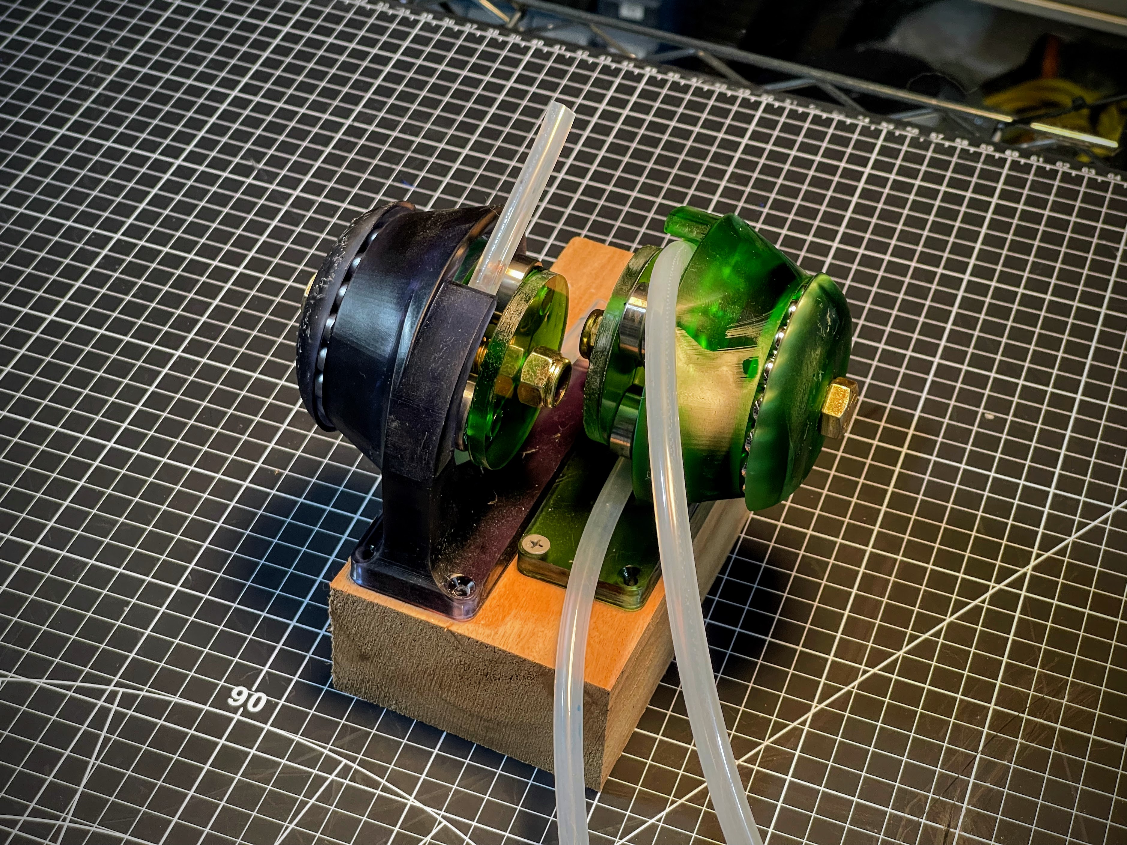
She ain't pretty (especially after a good while of getting knocked around), but the pic above shows the dual pump setup I rigged up for my testing needs. I was VERY pleasantly surprised that, other than a tweak to the hand wheel, these things worked pretty damn well!

I decided upfront that I was going to go with a resin printed build, because I thought the high stiffness and good surface finish throughout the 'pinch region' would give me a better chance. Since I was already going to have the good surface roughness, I might as well also integrate the main bearing into the printed parts.
In the image of the model, below, the Stator is the part shown in green, and the Rotor is shown in blue(ish.) Riding on the rotor are roller skate bearings to provide the contact with the tube. Race 1 has v-grooves on both sides of the race, providing the main constraint for locating the rotor, and Race 2 has a v-groove on the Stator, but only a single plane of contact on the Rotor side. This keeps from over-constraining the bearing.
 |
 |
The absurdly overkill bolt running through the center is a real showcase of "using what I had on hand" :) in that these were the only bolt/nut sets I had on hand with the length I was looking for.