
Objective
The general idea is for a flexure-based load cell design that utilizes the deflections within the flexural elements to mechanically display an indicator for the applied load.
The Concept
The idea is basically just for another ‘magnetically-assisted” flexure concept, but this one has pointers on it!!
For a first iteration, I was thinking I could just go with a compound flexure, (could even start with the Prusa Foot as a starting point) and put a pointer element at the mid-span on the leaf flexures. That should be the point with the highest angle of deflection.
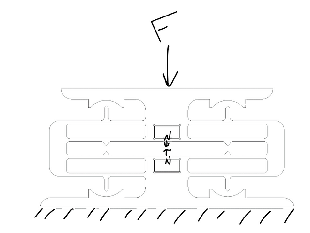
Below is the ‘hammock sketch’ that got the ball rolling on this one. However, there is a critical flaw in the design as shown in the sketch….can you see what I F’d up? :)
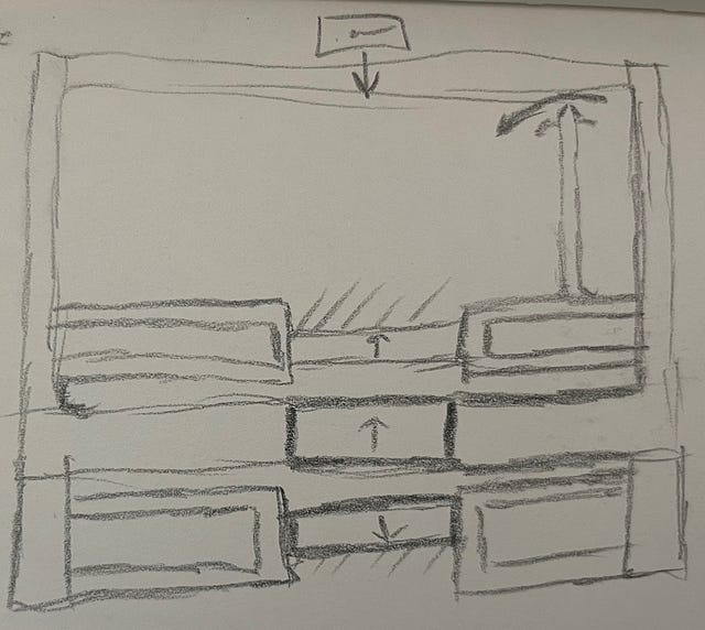
No? Fair enough, it’s hard enough to even tell what the hell I was trying to draw :D The problem is that, as depicted in the sketch, the flexure is over-constrained. This configuration of flexure is, more or less, a set of four individual ‘four link’ mechanisms. If you think of a conventional four link, one side stays fixed, and the free side maintains its relative orientation, but it’s center travels along an arc, as shown in the child’s sketch below.
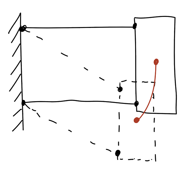
And it is this arc that is source of the flaw in the sketch up top. In that design, neither the fixed sides (here shown as the top and bottom magnet pockets, both are anchored to ground), nor the moving side (attached to the moving table) have freedom of motion to allow for the relative lateral (if looking at the four bar linkage sketch) translation of the elements through the flexure’s travel.
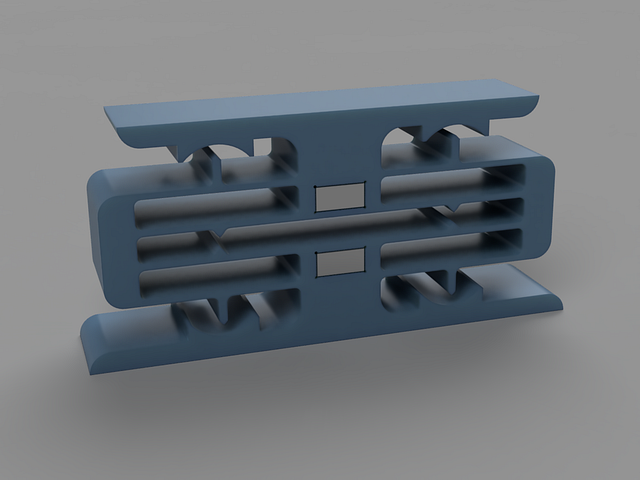
But anywho, the below images give a little better overview of the concept (I think/hope).
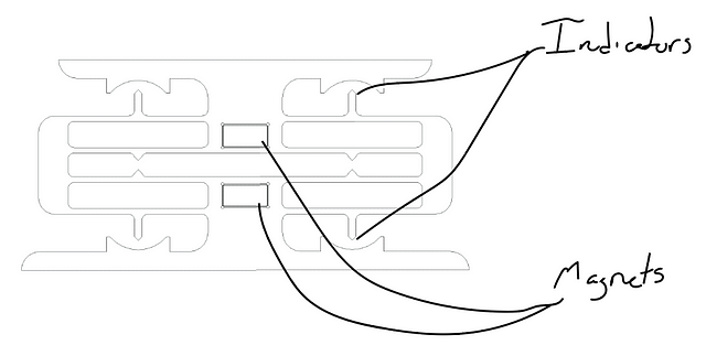
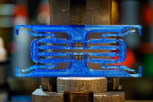
There are two magnets, one on each side of a symmetrical flexure. The magnets are oriented such that they repel each other, providing the bulk of the total stiffness in the direction of motion/measurement
As the flexures deflect, the ‘leafs’ will deflect into S-bends, with the midspan having the maximum angular deflection along the span. So it’s at that midspan point that we’ll add our little pointers! More info on the specifics of this design below under Rev 1.
Rev 1 Design
So here is what I cooked up as a quick proof of concept test design (yeah, I used this for the overview, so not really much of a reveal). Each of the magnet pockets measures 12(W)x6(H)x12(D), intended for Four (4) 12x3x6 magnets in each pocket (so eight magnets total).
One thing that might stand out with this design is that I’ve added pointers in far more locations than seems needed (or even reasonable), but it is VERY important for this flexure design to try to maintain symmetry as much as possible to provide the most linear motion profile (and therefore most accurate load measurement….although less crucial for this particular one I guess….but hey, I like symmetry anyway)
Concerns
My main concern with this design is that the deflection will be too small to give a reasonable “signal to noise” on the indicators. While I could calculate this angle, I honestly just don’t feel like it and want to submit this design for the Printables contest ending today ¯\(ツ)/¯ So instead I’m gonna just go for it and print one out! I shall report back (maybe)
Results
Yeah…..that concern was true :)….don’t you DARE point out my “could calculate it” comment….
I’m still actually pretty happy with it, in that it does still demonstrate what I was hoping to see. But I did move on pretty quickly to Rev2 :)
If you want to test it out yourself, you can find it on Printables
Rev 2
As feared, Rev 1 didn’t have quite the deflection one might desire to be even moderately useful :)
Enter Rev 2! But how to up the measurement deflection? Why, more flexures of course!
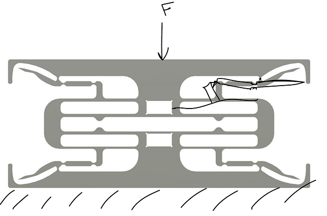
I replaced the pointers with linkages to some notch-type flexures to give a mechanical amplification (aka ‘lever’ )

The below shows….kinda….the expected deflection profile. As you can see (hopefully), the ‘pointer’ from the Rev1 design ‘pulls’ the linkage in toward the center. On the other side of the linkage is another notch flexure connected to the rigid frame element on top. If you aren’t familiar with notch flexures, they act (to first order) like a rotational hinge with the pivot point at the center of the thinnest portion of the notch. So this end of the linkage will be rotated around this pivot point, and so will its rigidly attached pointy end! So the tip of the pointers should rotate about their flexure center pivots. The movement of the pointer will be equal to movement of the linkage multiplied by the ratio of the Pointer Radius : Linkage Radius, which I configured here to be 8:1. So that SHOULD mean that what we have is essentially an 8x ‘gain’ on our sensor! :)
Concerns
So, what could go wrong? My main concern with this one is that the indicator linkages and their associated flexures are too large of a portion of the total stiffness of the mechanism. There is also an imbalance in stiffness between the “inner” and “outer” flexure sets. My concern is that these effects may now be significant enough to cause issues. The best way to address this would be to 1) drastically reduce the stiffness of the indicator flexures relative to the ‘main’ flexures, and 2) compensate the ‘inner’ flexures’ stiffness to compensate for the parasitics caused by the indicators. Instead of adding some sort of mirrored flexure set, I would probably just calculate the appropriate change to the thicknesses and or lengths of these leafs such that their effective stiffness matches the effective stiffness of the full set of stuff goin on with the others.
But alas….I am already designing these flexure webs at about the limit of thinness that I’m comfortable with printing for these quick test/concept prints. And I don’t want to increase the main flexure stiffness because a key aspect of this concept is maintaining the magnets as the dominant source of stiffness in the direction of measurement. And for the latter….I just don’t feel like it. While I very much enjoy playing with these, I don’t know that I like it enough to do ‘real work’ :)
If you DO want to calculate optimal flexure parameters (or at least a rough estimate….the anisotropy of printed parts breaks a pretty good set of assumptions in most of equations) this book is my absolute go to for such things. Or, if you want to go hardcore and even build the model to account for the printed materials, you could give this one a go :). While I do own both, I honestly pretty rarely open the second (sorry Stuart!)
Results
Wellllll….. :) While it manifested in a slightly different way than I expected, it was indeed the stiffness of the indicator flexures that was my undoing…but always a pleasant surprise to fail in an unexpected way! The issue ultimately was much more localized than I expected. The stiffness of the indicator flexures causes the leaf flexure to not give us the S-bend we are banking on…instead it essentially splits the leaf into TWO leaves, each one doin it’s own damn S-bend and keeping the center span level. I should point out that 1) I am exaggerating some in that last comment to paint a picture of the motion…did you see it? Was it pretty?…But anyway, because there is still a ratio of stiffnesses at play, there is still SOME deflection in the desired direction, but it’s very small. and 2) I should also clarify, that all of this is based only on visual observation of the deflection (aka, “I looked and squeezed”, but don’t worry, I did so a statistically significant number of times, I assure you) and back of the envelope analysis. So please feel free to correct me if you catch something I got wrong, but bring calcs….I never said it was fair ¯\(ツ)/¯
Rev2b
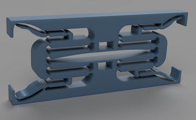
Not a ton changed here. I swapped out the leaf springs for a collection of notch flexures. Little aside, but this is actually more in line with how I would generally design this type of flexure ‘for real’, or at least it would be for a metal flexure being traditionally machined. Notch flexures are MUCH easier to machine than leaf flexures, unless you are fortunate enough to have a Wire EDM machine with some downtime :).
By moving to notch flexures, the midspans are now rigid bodies (or at least can be assumed as such for our purposes here). So this will provide a much more predictable deflection for our indicators.

Concerns
My general concerns from before about flexure performance degradation caused by the interplay of the indicator flexures and main flexures remain, but not significant for the purpose here (if I were trying to build a positioning system, for example, this would be a MUCH bigger concern, since my assumption is that this will primarily present as parasitic motion(s).)
The only new concern that I have added for myself here is related to the clearance cuts I had to add in the center to keep the inner flexure bodies from reducing our range of travel. The problem that this presents is in how it will impact the location of the pivot points for those hinges. Any asymmetry within a notch flexure will impact where the center of rotation lands for that flexure. If you go back to the four link discussion up top, you may see that having the arms of the four link being the same length is critical for that mechanism to give the motion profile we’re aiming for (fun aside, but you can also use this “problem” to your advantage by introducing a prescribed rotational motion by intentionally varying these lengths.) And so here in lies my concern. The movement of the inner flexures pivot locations due to the asymmetry means that the inner and outer links will have different arm lengths…not ideal! My assumption is that the amount of deviation in axis location for this specific asymmetry isn’t going to move the rotation axis any more than my manufacturing tolerances already are. The basis for this assumption is that the amount of asymmetry of the notch along the axis that we’re most sensitive to (left-right on the above image) is very low. There is significant asymmetry on the other axis, however, this will just cause the pivots to move in a direction that does not impact our performance here.
Results
Well, if you saw the gifs up top, you get the gist :) This one basically demonstrates exactly what I was hoping! So at this point, I’m going to call this series done, at least for the time being. Happy to hear ideas for improvements, questions, or whatever else ya think may be of interest!