Assorted (hopefully) "Useful Stuff" Projects
Like the bucket of assorted fasteners on that bottom shelf, this category is for stuff that I didn't know how to group...oh, and speaking of those fasteners, check out the little sortin fella!
2020 Aluminum Extrusion Hardware
|
Quick Bolt Sorter
|

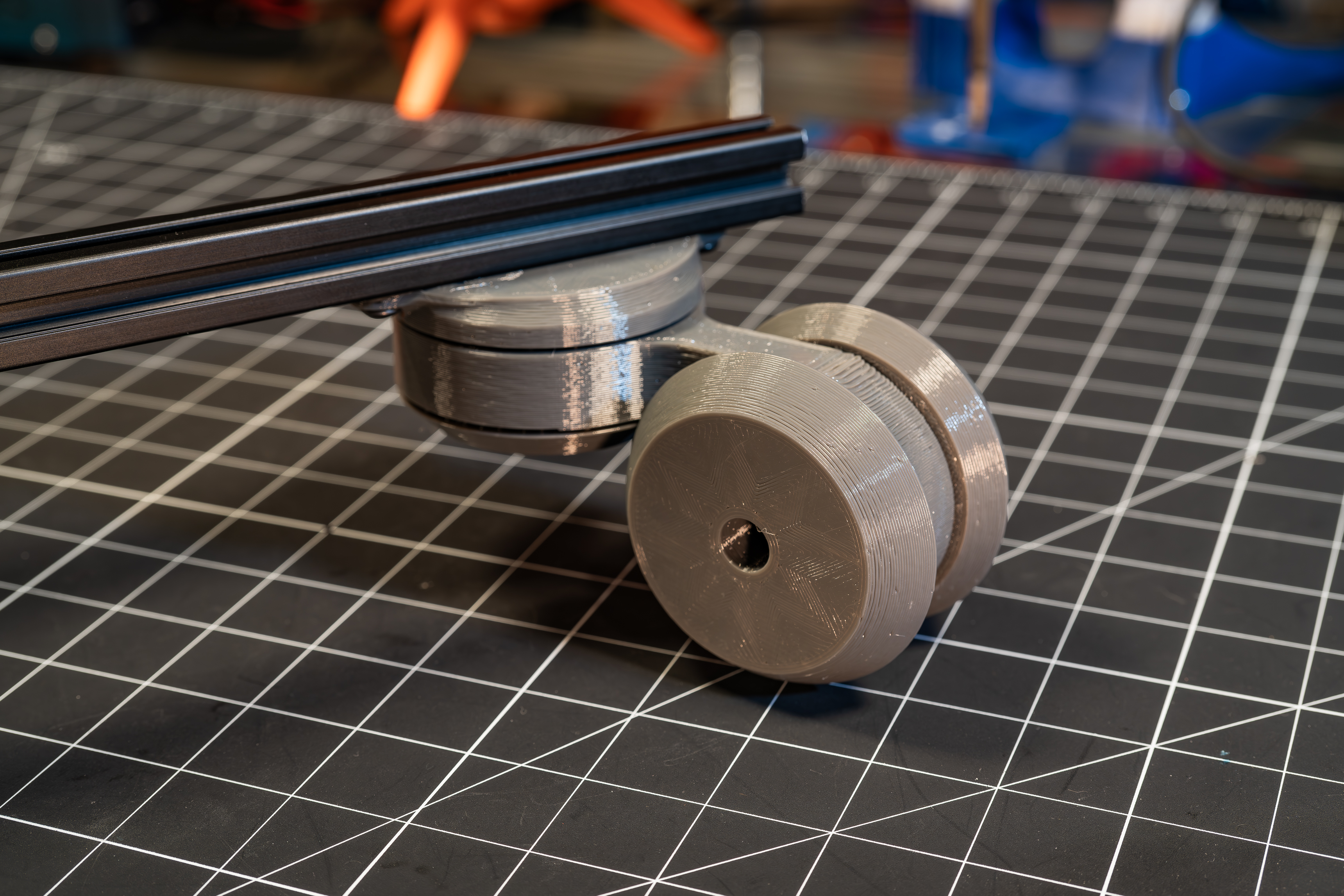
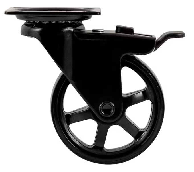
General Purpose Turntable - Gen1
- Details
- Parent Category: BubsBuilds Projects
- Category: Assorted (hopefully) "Useful Stuff" Projects
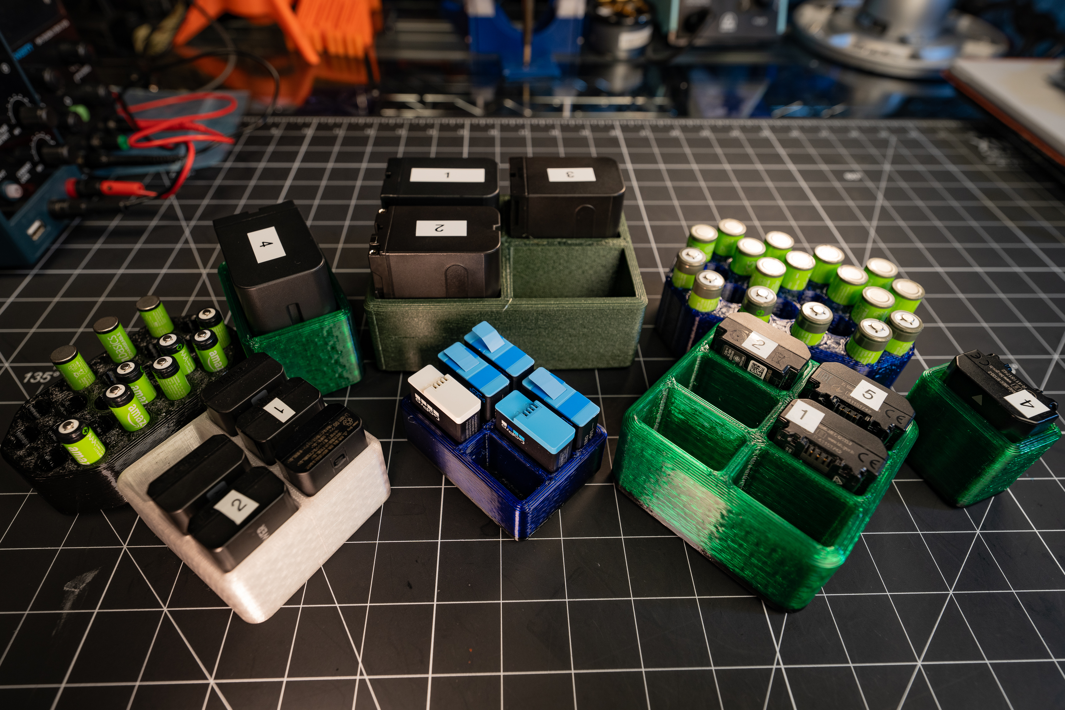
Common Batteries
AA
AAA
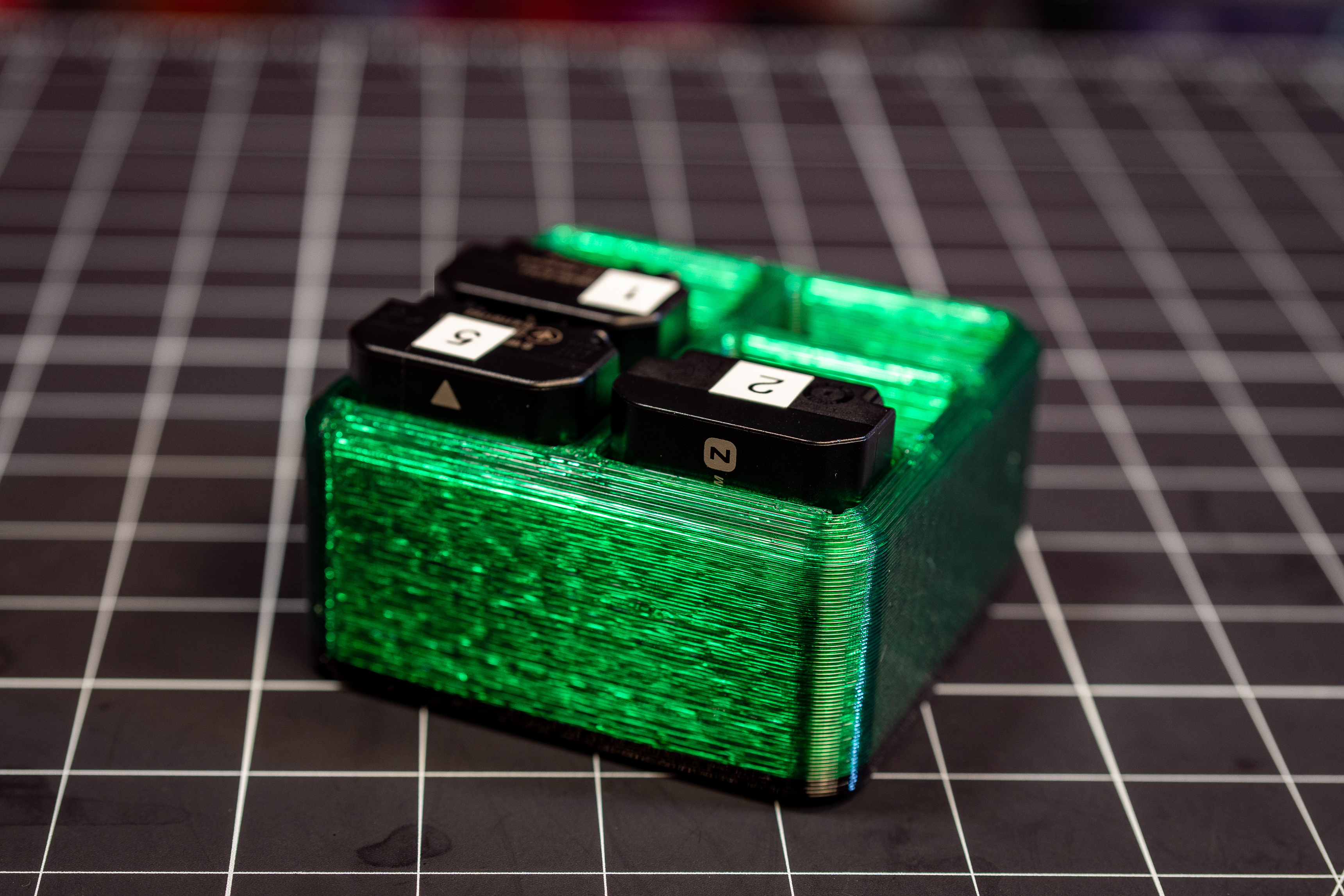
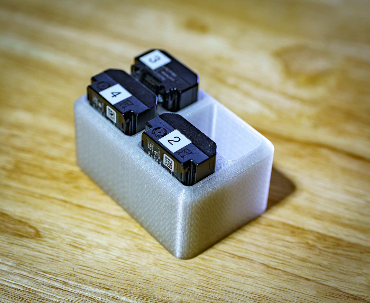
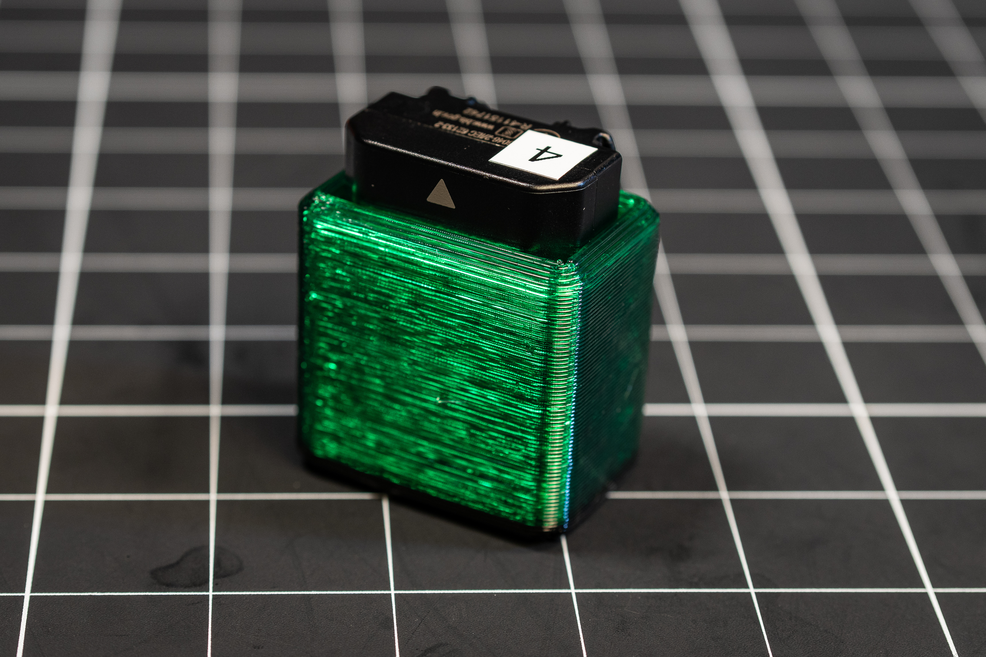
Camera and Related Batteries
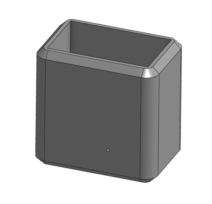
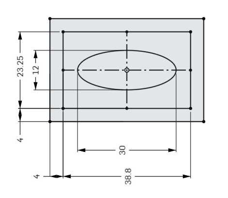
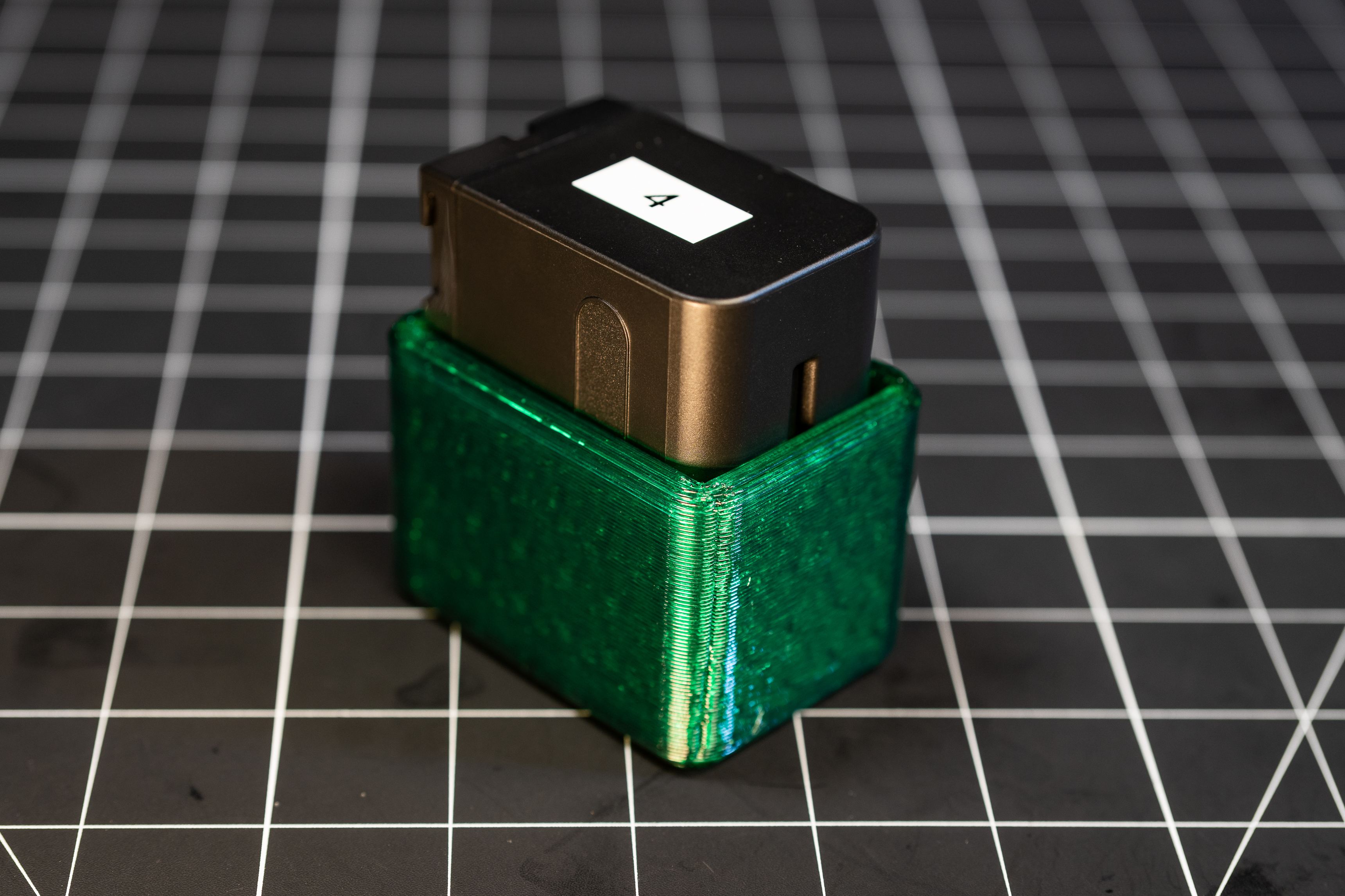
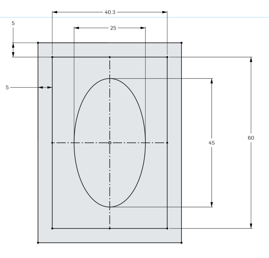
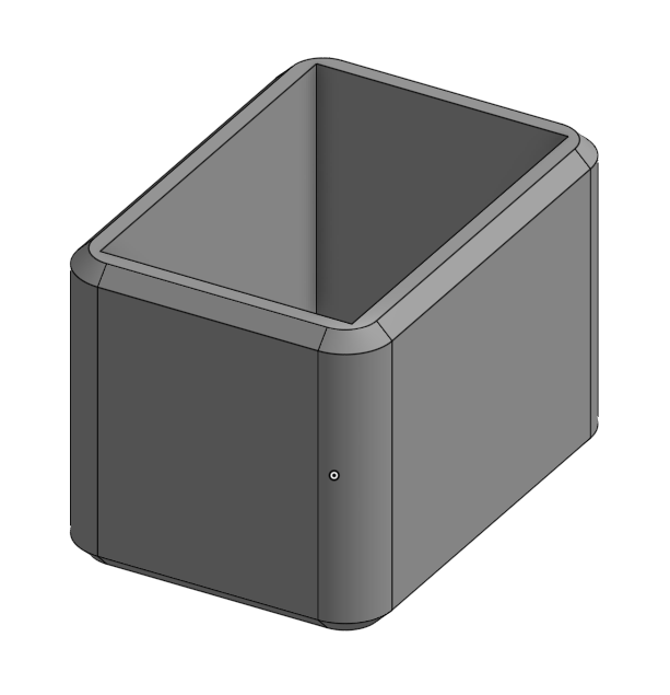
Sony NP-FZ100
Six Slot version
Four Slot version
Single
Sony NP-F970
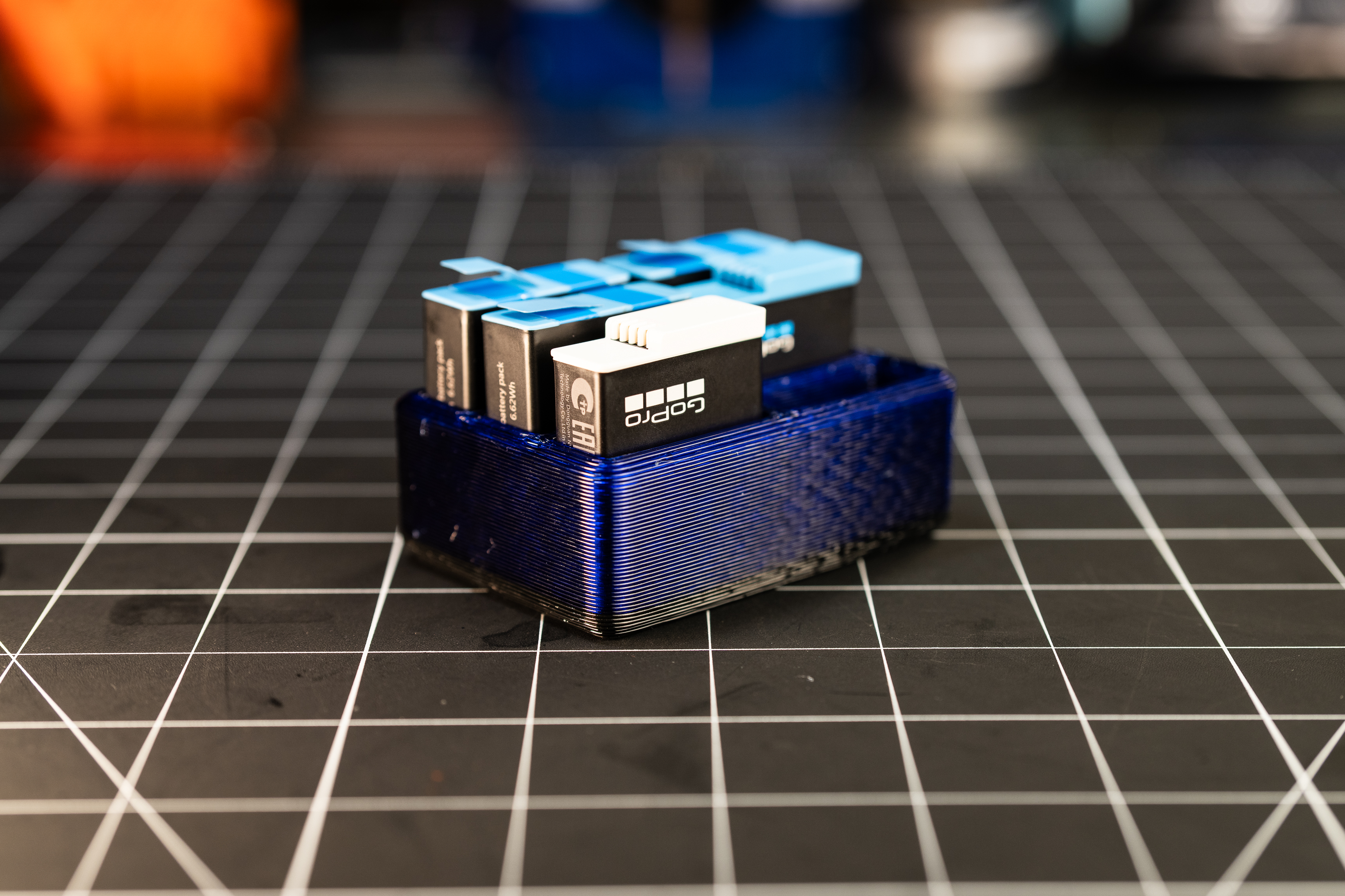
GoPro
- Details
- Parent Category: BubsBuilds Projects
- Category: Assorted (hopefully) "Useful Stuff" Projects
Update - Load Testing to failure
Build
BOM
- Printed Parts
- FrameMount
- Hub
- Retainer
- Wheel (x2)
- COTS
- (2) M5 heat set - I used short ones
- (30) 9.5mm balls - I use this 3/8" slingshot ammo...kind of alot.
- (2) M5x10 Fastener - I used a couple BHCS
Design
CAD files available on OnShape, here.
 |
 |
 |
Design Notes
V1 - Epic fail
V2
2024/01/12 - Design notes
2024/01/13 - Design notes
- Good lord was this thing a pain in the ass to assemble! The configuration of the main bearing allowed the balls to easily fall too far out of position to be self-aligned during preload...aka balls went f*&%ing everywhere :)
- The wheel bearing, however, was substantially easier and self-aligned quite well in repeated tests.
- The wheel bearing could use a better-defined preload. I inserted stacked washers in between the wheels to set the spacing, but ended up going with basically zero preload in the bearing. Although this makes the bearing pretty sloppy, I'm not sure I actually mind for this application. As long as it stays assembled and allows free rotation, I don't really care about runout. May go with an intentional zero preload design for V3.
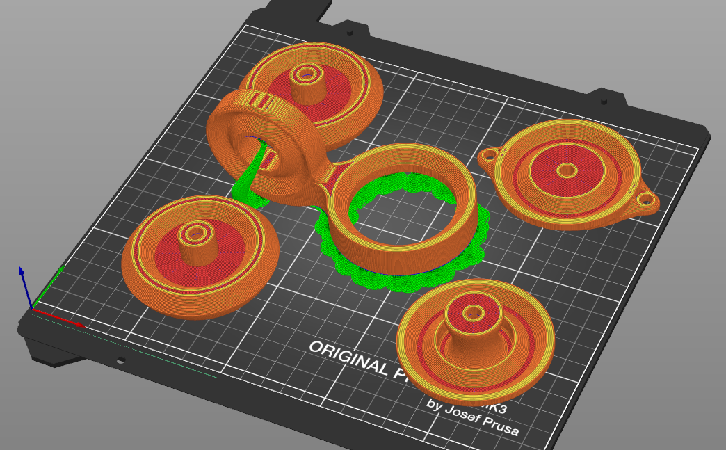
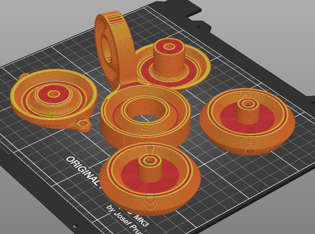
- As usual, support structures suck :) Although not a significant problem to remove on this one, I really don't like having the decreased surface finish so close to the bearing race surface. Changing the geometry to get the outer diameter of the main bearing race is tangent to the flat on top of the wheel bearing (to remove the ring of supports shown in the above screen shot.
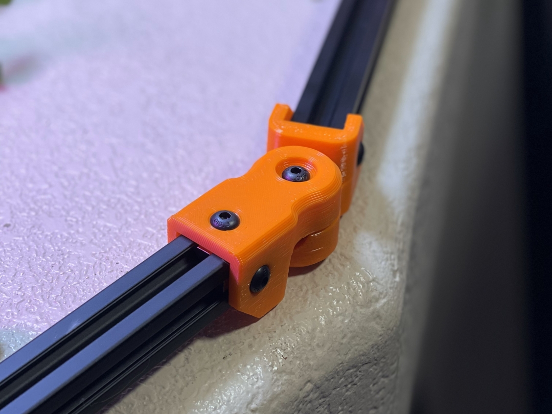
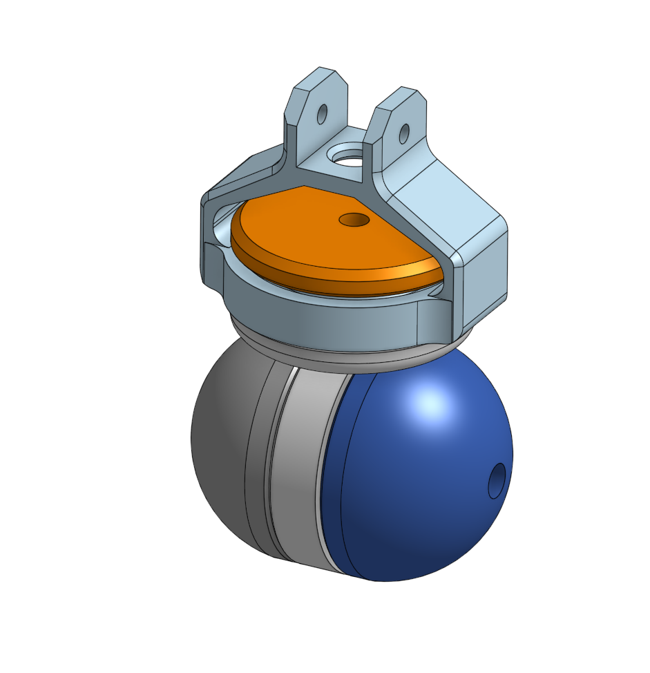
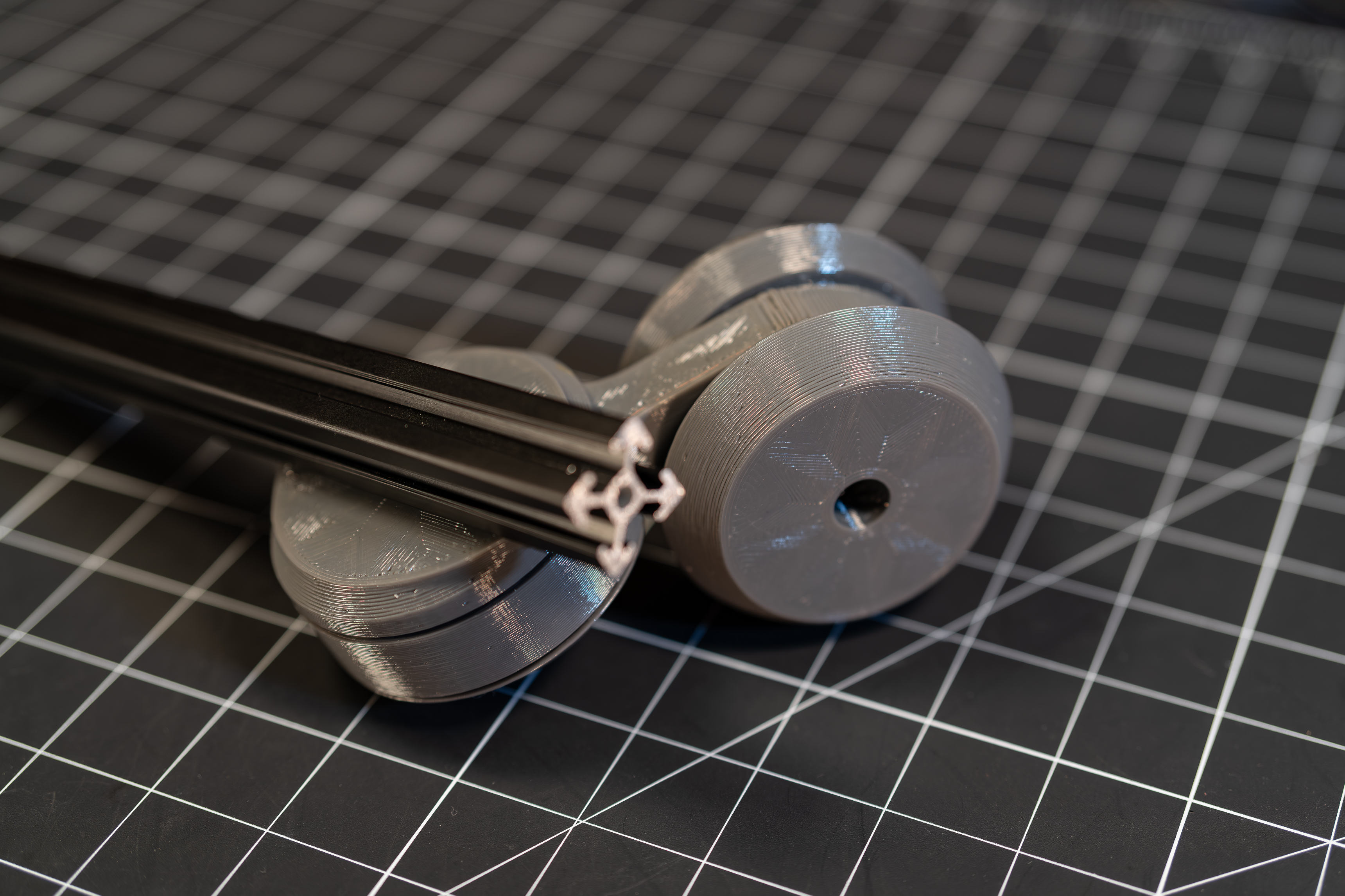
- IT CASTERS (I know this isn't actually a verb...but hey, it's the internet, I can make up whatever I want, right? :) ). Other than the assembly woes, it does indeed function as desired! No clue what a realistic load operating range it will be suited to, but at least it does it's base function.
V3
2024/01/14 - Design notes
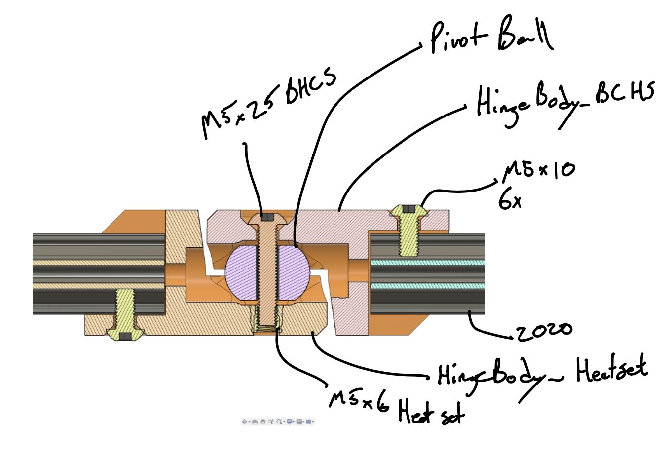
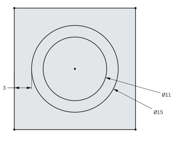
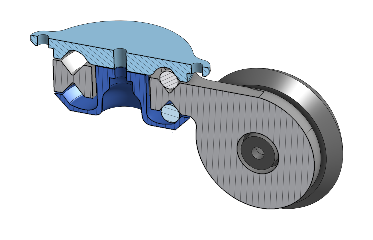
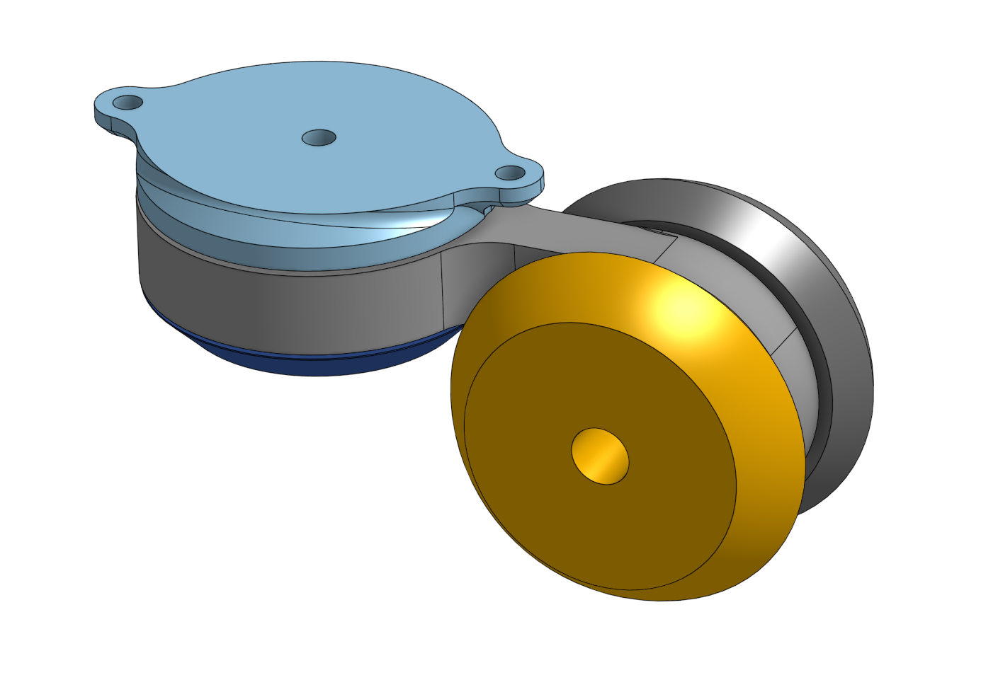
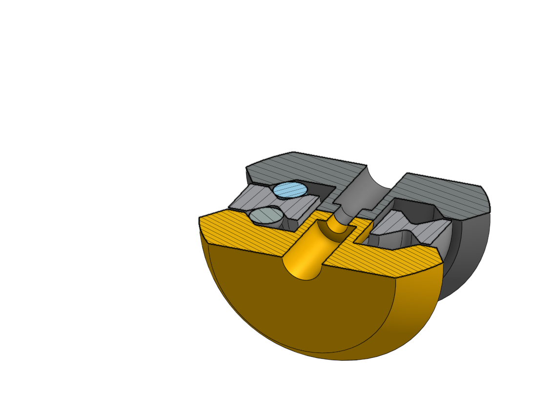
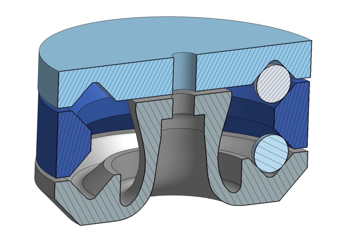
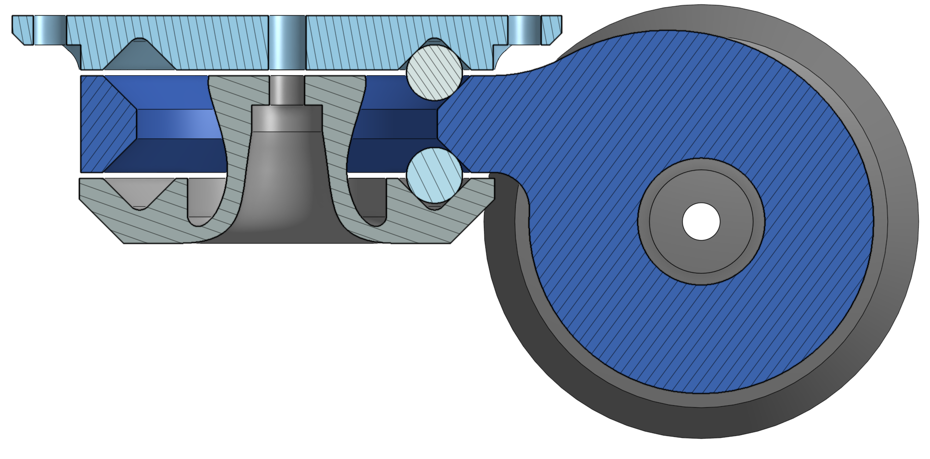
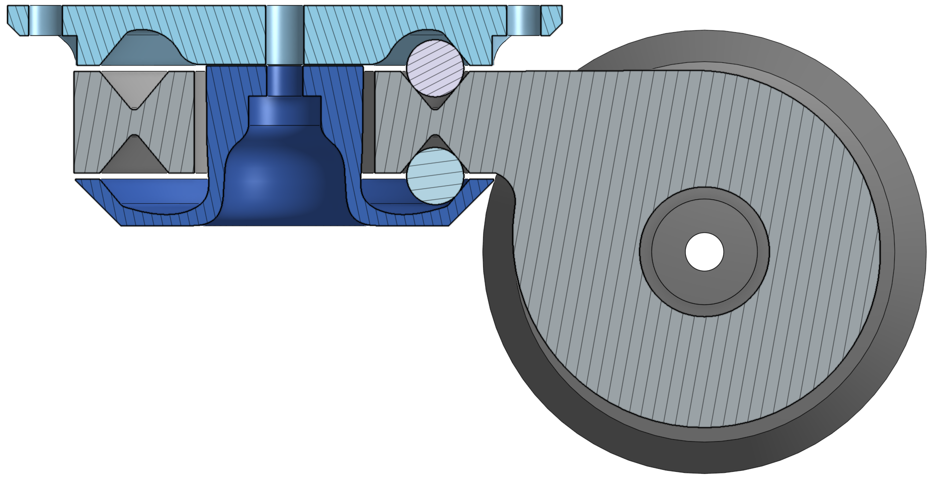
- The main issue with V2 was with the reality of assembly for the main bearing. Although it is full constrained when assembled, it was an absolute nightmare keeping the balls in their races while putting it together. Since the wheel bearing assembly was substantially easier to work with, I'm going to replicate that bearing configuration for the main bearing as well. The below cross section shows the revised bearing along side the V2 config. Essentially it moves the ball plane definition to the Hub, instead of in the FrameMount and Retainer.
- Also visible in the below cross sections, the wheel axis was moved down to make the outer diameter of the wheel race tangent to the top surface of the main bearing race
 |
 |
- Details
- Parent Category: BubsBuilds Projects
- Category: Assorted (hopefully) "Useful Stuff" Projects
V1
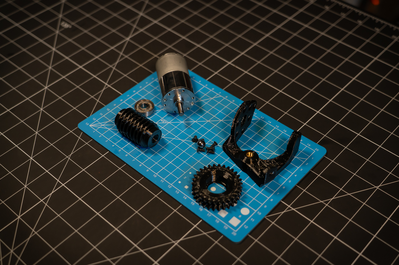
Build
BOM
-
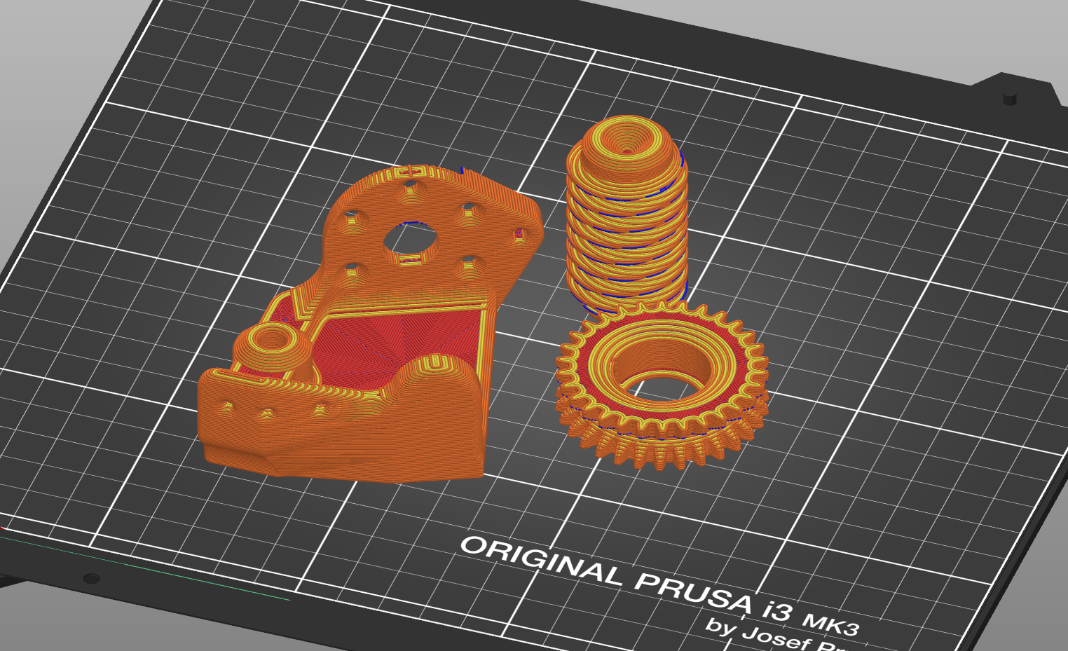
Printed Parts - I printed mine from Sunlu PETG
-
(1) Bracket.stl
-
(1) Worm.stl
-
(1) WormGear.stl
-
-
- (1) 608-2RS bearing (aka roller skate bearing)
- (1) 9.5mm bearing ball - I use this 3/8” slingshot ammo
- (1) M5x9.5 heat set
- (1) M5x12 Flanged BHCS (or whatever head ya please, but head diameter must be >8mm)
- (1) Greartisan DC gear motor - I have now played around with everything from 20RPM to 550 and both 12V and 24V. For my blinds project, I’m going with the 24V/200RPM version. FYI, pretty sure the 20RPM is more than sufficient to completely destroy the winch…enjoy :)
- (3-6) M3 Flat head screws - For holding the motor. It has 6 mount points, but 3 should be plenty.
- String - I used this fishing line, which is awesome, but kinda pricey.
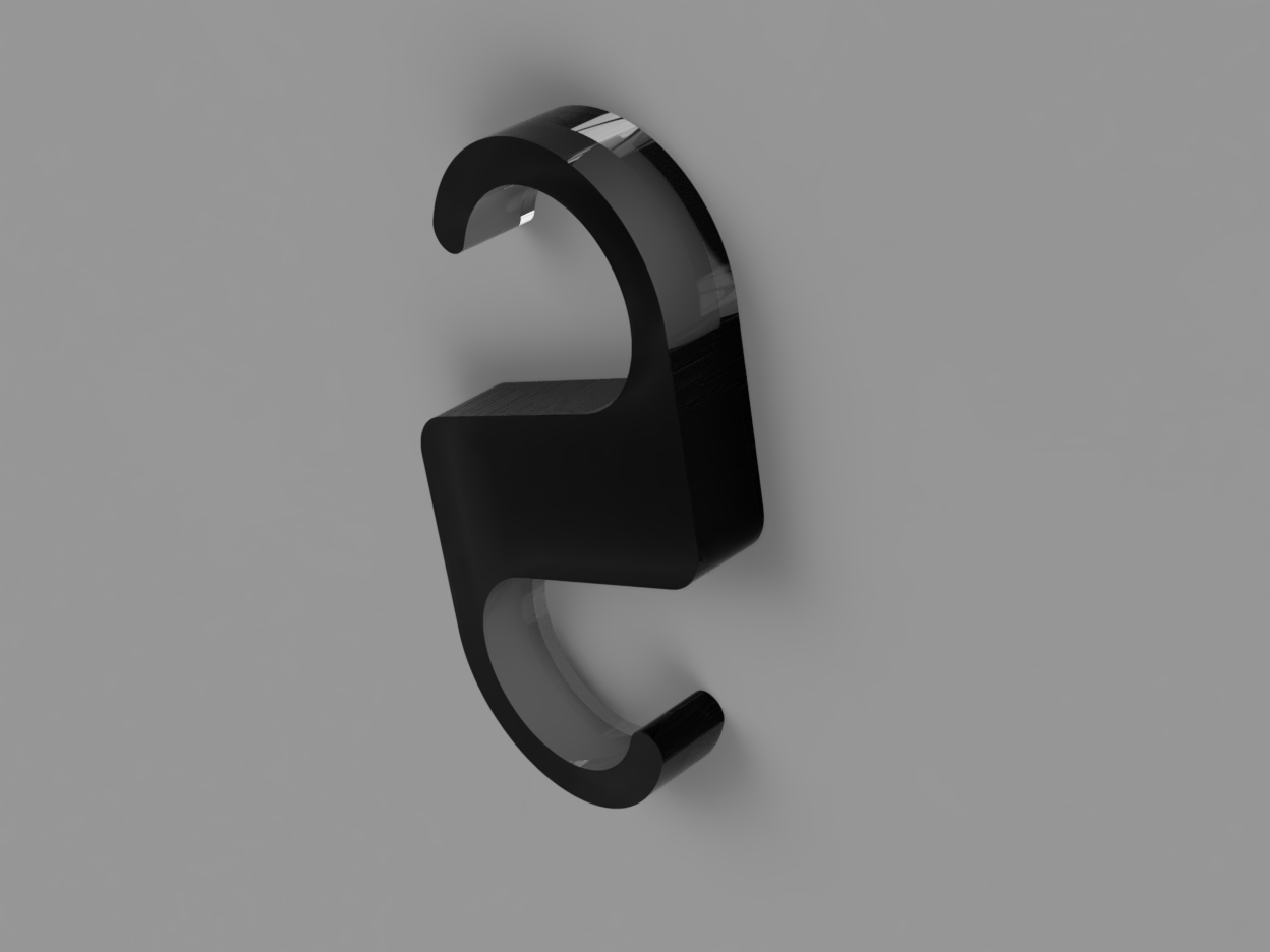
If you need/want hooks for the ends of your winch, I reused these little hooks that I previously made for cable organizing. They are the “CableHook.stl” file included in the model repo.
Build
-
Print the printed parts….obviously
-
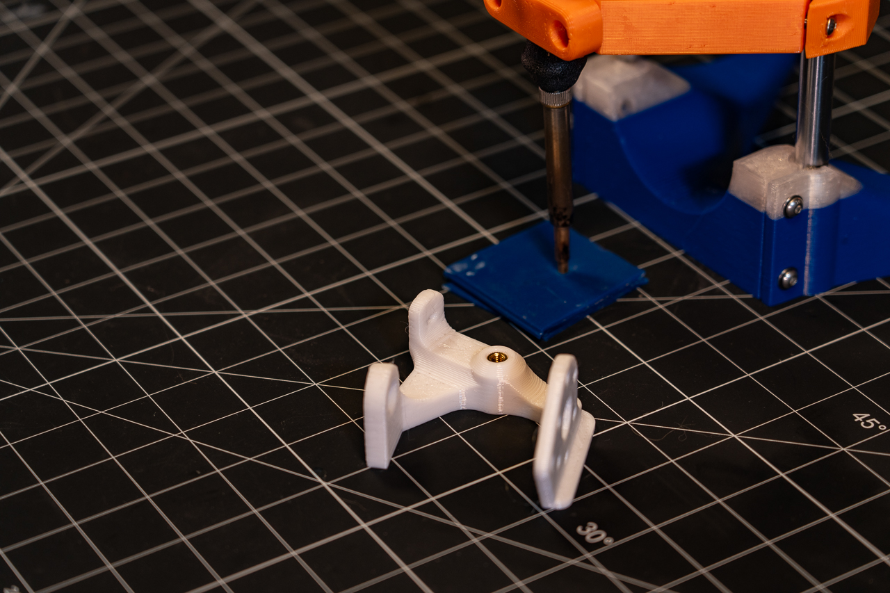
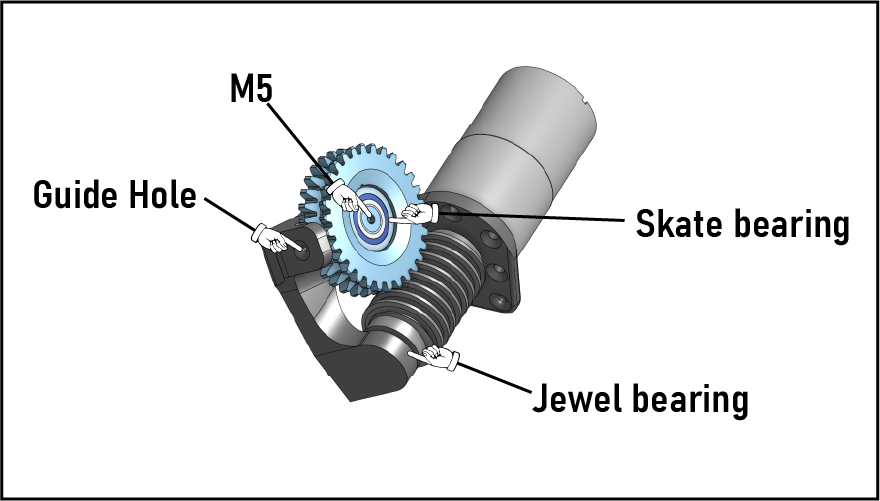
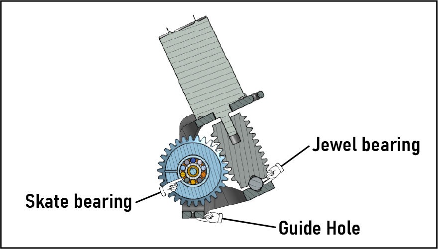
Insert the M5 heatset in the Bracket
-
Place the 9.5mm ball in the cone on the end of the worm and then put this sub assembly inside the bracket, nesting the other side of the ball in the cone of the bracket to complete the jewel bearing.
-
Hold the sub assembly from 3 so that the hole in the worm is aligned with the motor axis opening. Look and see the orientation of the D flat on the hole in the worm, and bring in the motor with its D flat aligned to the hole.
- NOTE: you may want to check the fit of the motor shaft on the worm prior to assembly. This is intended to be a pretty tight fit, and anything obstructing the opening will make it difficult or impossible to assemble without damaging something.
- You can put the assembly with the back side of the jewel bearing against a flat surface to press the motor into position. Don’t push TOO hard on this, the motor’s thrust bearings likely aren’t particularly high quality.
-
Attach the motor with at least 3, equally-spaced M3s. I would recommend tightening them in stages, working around the bolt pattern. If there is additional travel in the shaft-to-worm fit, this will draw it in evenly.
-
Thread string through the small hole in the worm gear from the outside. You only need enough string on the side to be able to hold onto as you insert the bearing.
-
Hold the string segment on the ID such that it sits in the small V-groove along the ID. With the string held in place, press in the roller skate bearing until it seats against the gear. For my builds thus far, this has been sufficient to hold the string in place, but if you want some extra peace of mind, you may want to tack it to the side of the gear with some superglue.
-
Wrap the desired amount of string around the pulley inside the worm gear. Try to keep even tension to get a consistent winding and do make sure the wrapped string does not sit so high in the groove that it might obstruct the gear mesh. It will work with the string wrapped in either direction.
-
Feed the free end of the string through the guide hole in the bracket. Mesh the worm gear with the worm and align the bearing hole with the heat set. Try to keep some tension on the string as you work with the assembly to avoid future tangles. Insert and tighten the M5 to secure the worm gear in place.
- NOTE: The worm gear should be mounted with the smaller opening side facing the heat set.
-
Attach string to the fixed attachment point.
-
Have fun and let me know how it came out!
Design
Design files are available here on OnShape
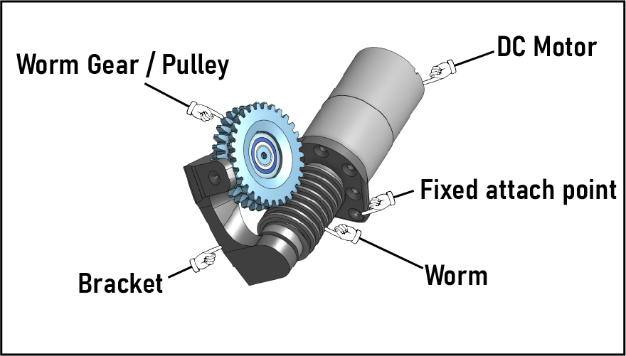
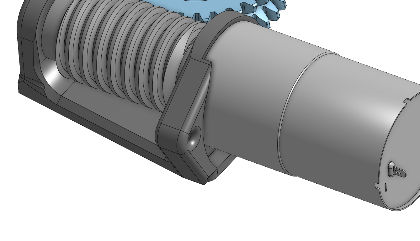
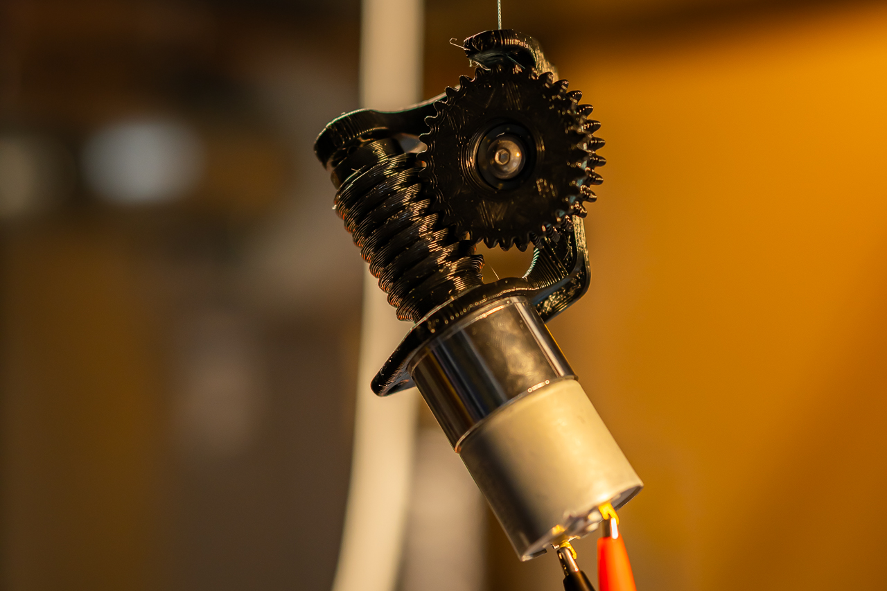
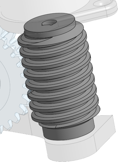
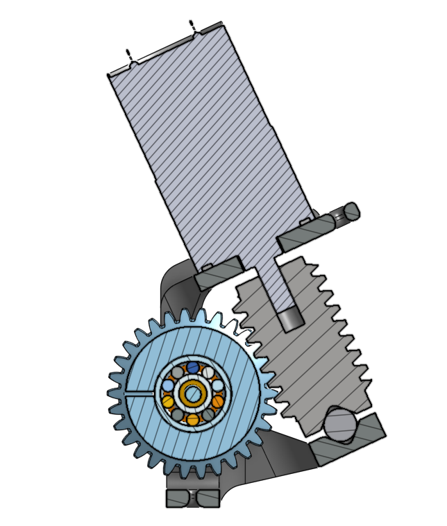
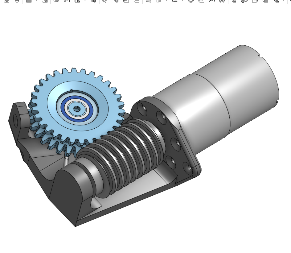
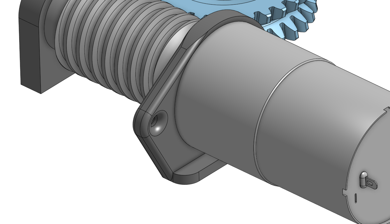
Essentially this design is just a worm gear drive mechanism with a groove cut into the worm gear to act as a pulley.
The Worm is supported on one side by the motor’s internal bearing(s) and on the other end by a jewel bearing formed by cones in the Worm and Bracket, with a 9.5mm bearing ball between them.
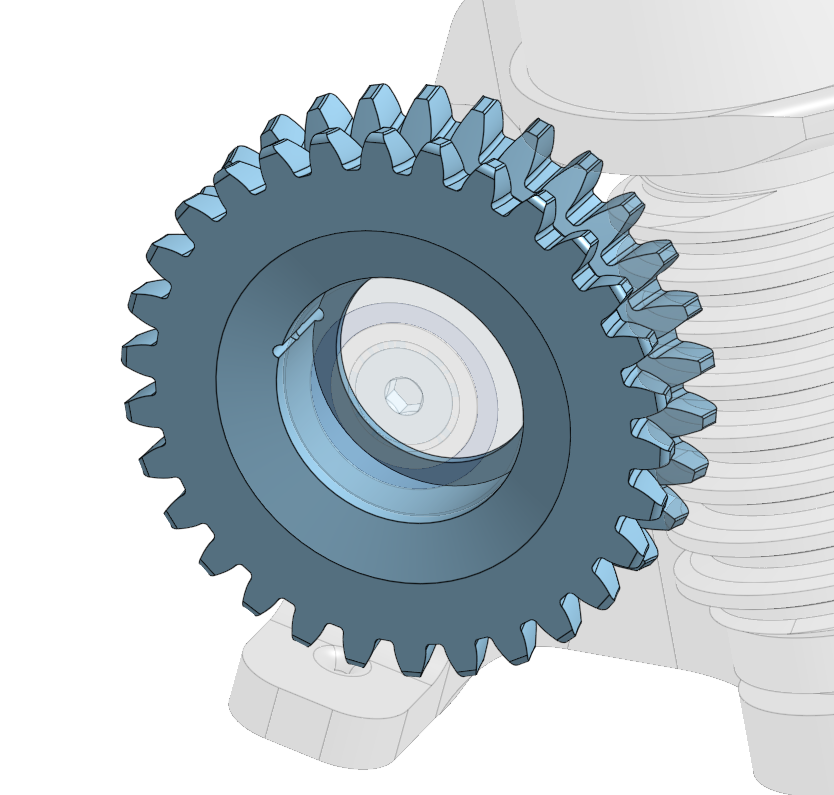
The worm gear (and pulley) has a roller bearing with a snug fit at it’s centerline, providing radial support. The expectation is that the string will provide a self-centering force axially, so no axial/thrust support was included.
V2
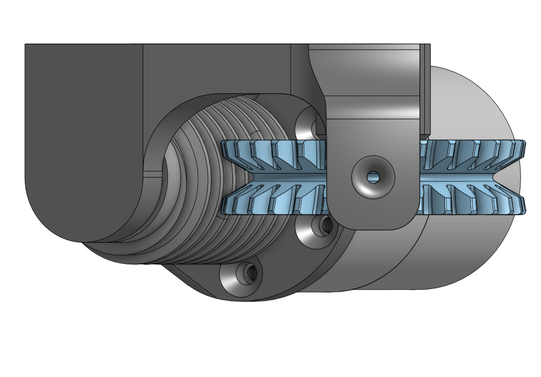
Gear Mesh
Tightened gear mesh 1mm by translating axis of Worm.
 |
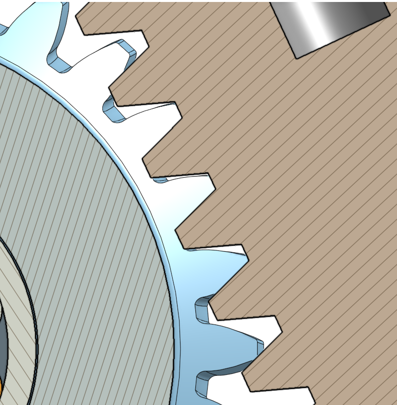 |
I went with a slight interference at nominal, since I expect an offset in the Worm Gear axis due to the clearance fit between the bearing and fastener (assuming the force from the worm will ultimately seat the bearing on the far side of this clearance).
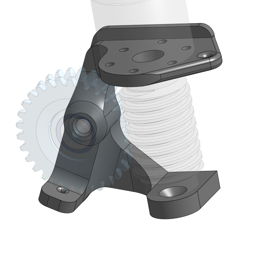
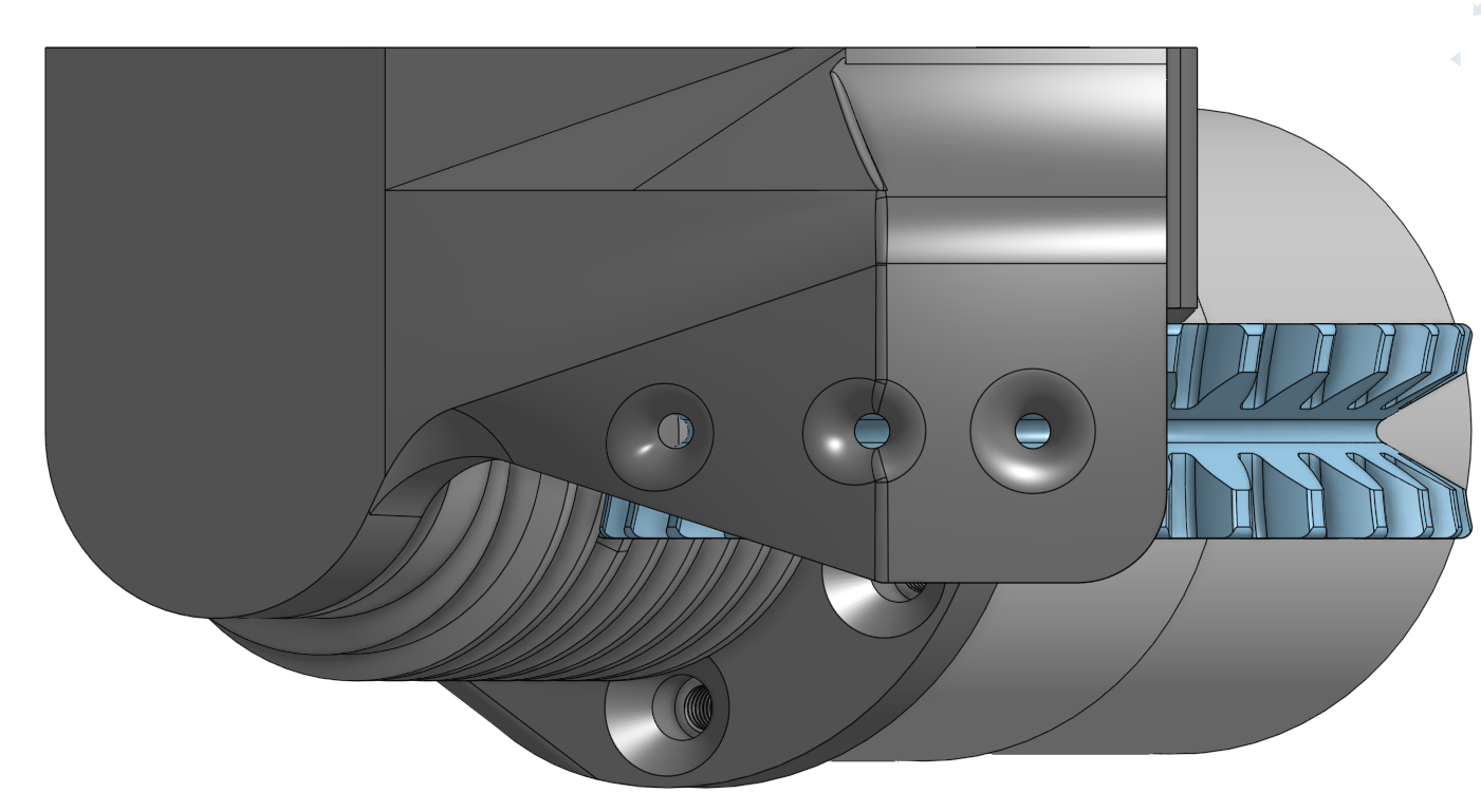
Backplane
In testing rev1 build2, I noticed the C frame was opening up somewhat due to the side load from the string tension against the guide.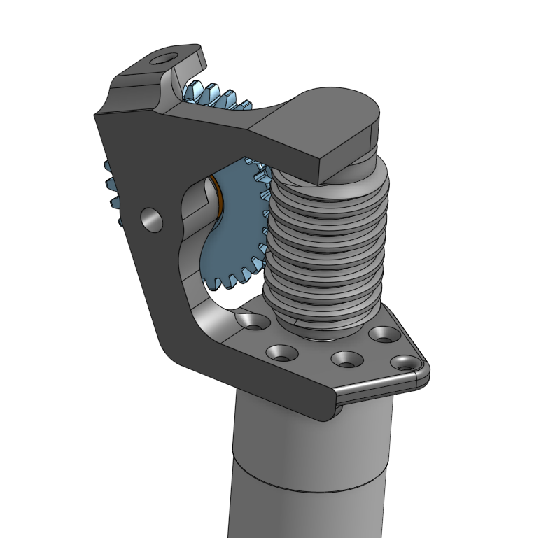
To mitigate this, I’m going to make a couple of additional small tweaks. The first is to add a back plane to fill in the C frame. So I basically just filled in that empty space with a 5mm thick plate and added some healthy fillets at both the motor and jewel bearing end.
Adding this material cost me one of the mounting holes for the motor…guess I’ll somehow have to make do with only 5.
Guide hole location
Initially I just set the guide hole at the centerline of the spool, without really giving it much thought. But I realized quickly that while this allows the spool to be loaded in either direction, it also puts a significant amount of load into the guide (and also will probably wear both the guide and the string pretty quickly).
So I decided to move the guide hole closer to tangent to the pulley….at first… Then as I started modifying the model, I realized it might be nice to just leave the existing hole and add options!…plus I am a terrible designer, and changing the previous hole placement by THAT much breaks everything :)
So I basically just tied the guide to the jewel bearing support with a loft feature and added two more guide holes at 10mm and 20mm offsets from the pulley axis.1.5 mm
Using the guide holes closer to the tangent will not only reduce the side load into the guide, it will also move the line between the two attachment points closer to the expected CG. So there should be less rotation of the assembly as the cable tensions.
Fixed Attach Point
Final modification for V2, a beefening of the attach point for the fixed cable. I didn’t have any issues with this in V1, but with the string pulling directly in shear along the layer lines, I just felt like a little bit of reassurance would be nice.
The existing wall was 5mm thick, so I just added another 5mm to that surface. The load path down into the frame isn’t ideal, but I think it’s good enough.