Tool-related Projects
- Details
- Parent Category: BubsBuilds Projects
- Category: Tool-related Projects
Design
Objectives
- Apply both tensile and compressive loads of up to 2.5kN (~500 lbf) - Admittedly, this was selected somewhat arbitrarily, but seemed achievable at a reasonable price and sufficient for the vast majority of my needs...at least for now
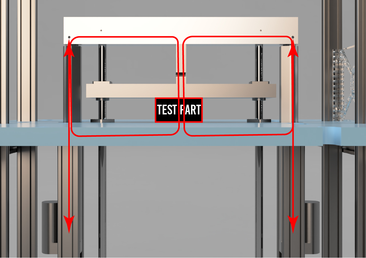
- Withstand offset loads - Because I will be testing 'real' parts, I can't assume that loads will always be along a single line of action. Unlike standard test samples, which can be designed/held such that loads are well-behaved and nominally symmetric.
- Data collection
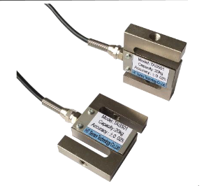
- Load - I'd like to have a configuration that will support a somewhat modular load cell. This will allow for using load cells that are sized for the part under test, enabling a wide range of applied loads while still getting good signal-to-noise when needed (for example, when testing a small bracket, I may want to only use a load cell with a total range of 100s of Newtons, but if I'm trying to test something bigger, I may want a full scale range of 3kN).
- Displacement - At a minimum, I want to be able to measure the amount of strain being applied to the part under test. Ideally, I'm thinking I'd like to have at least three displacement measurements
- One measurement of the strain in the part. For this I'm thinking I'll consider the dsplacement between the load plates as this strain (the interfaces where the load will be passed into the part).
- Two measurements for the actuators (one for each). Ultimately I want to be able to run the linear actuators closed-loop from positional feedback.
- Temp - Cause always. I've been working in precision stuff for too long, what can I say
- Imaging - In addition to wanting to be able to get photos and video for my own enjoyment, I also would like to attempt to use an image-based system for some of the displacement measurements mentioned above.
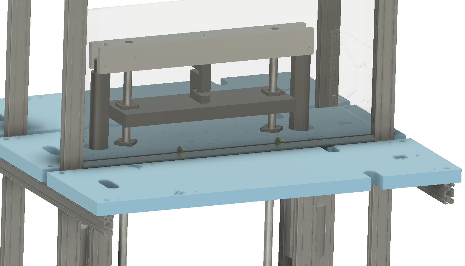
Design Overview
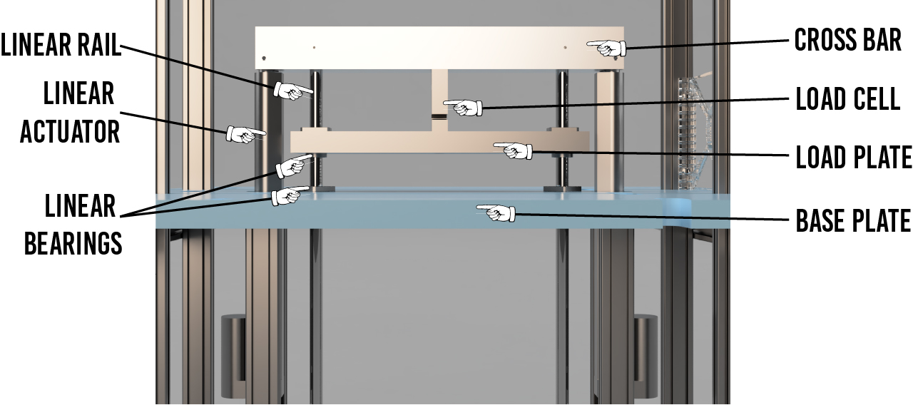
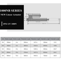
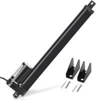
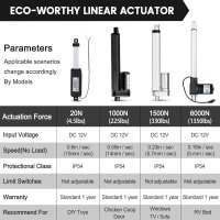
Actuation
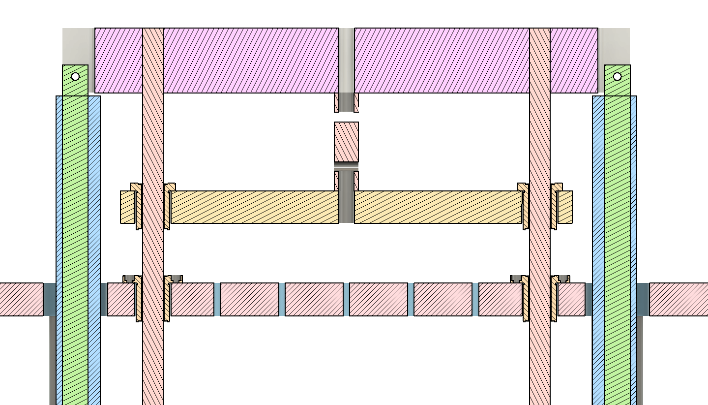
Linear Guides
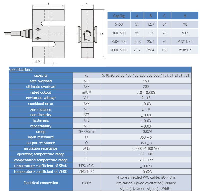
Load Cell
- Details
- Parent Category: BubsBuilds Projects
- Category: Tool-related Projects

Objectives
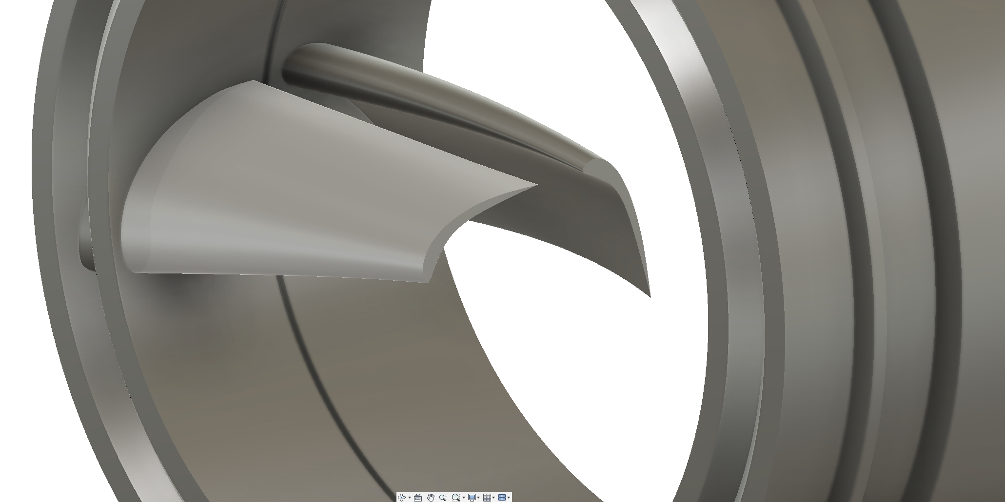
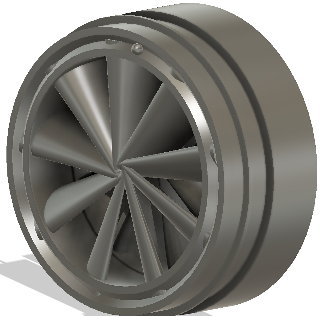
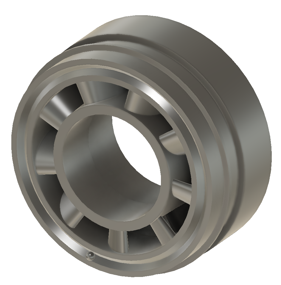
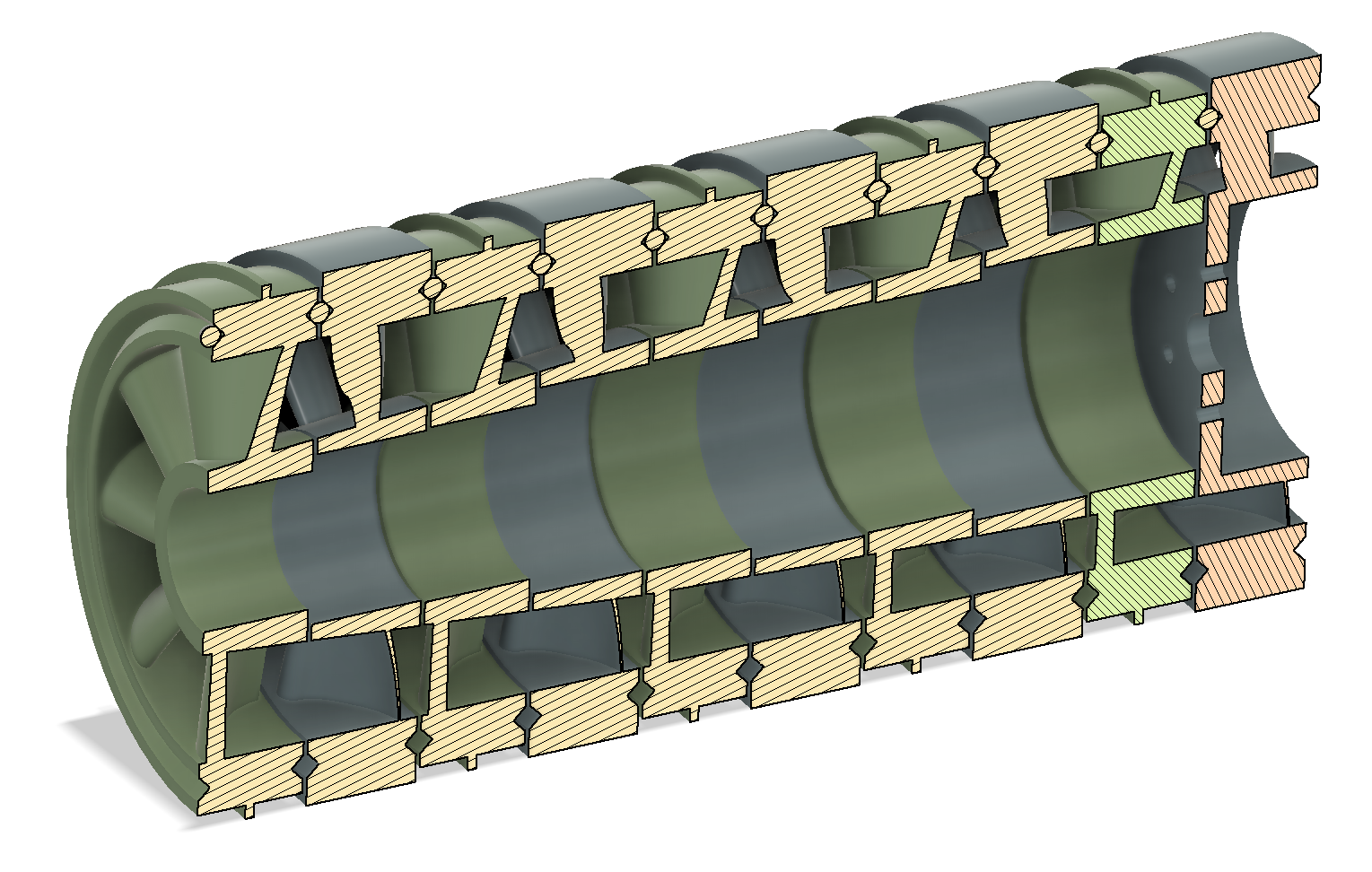
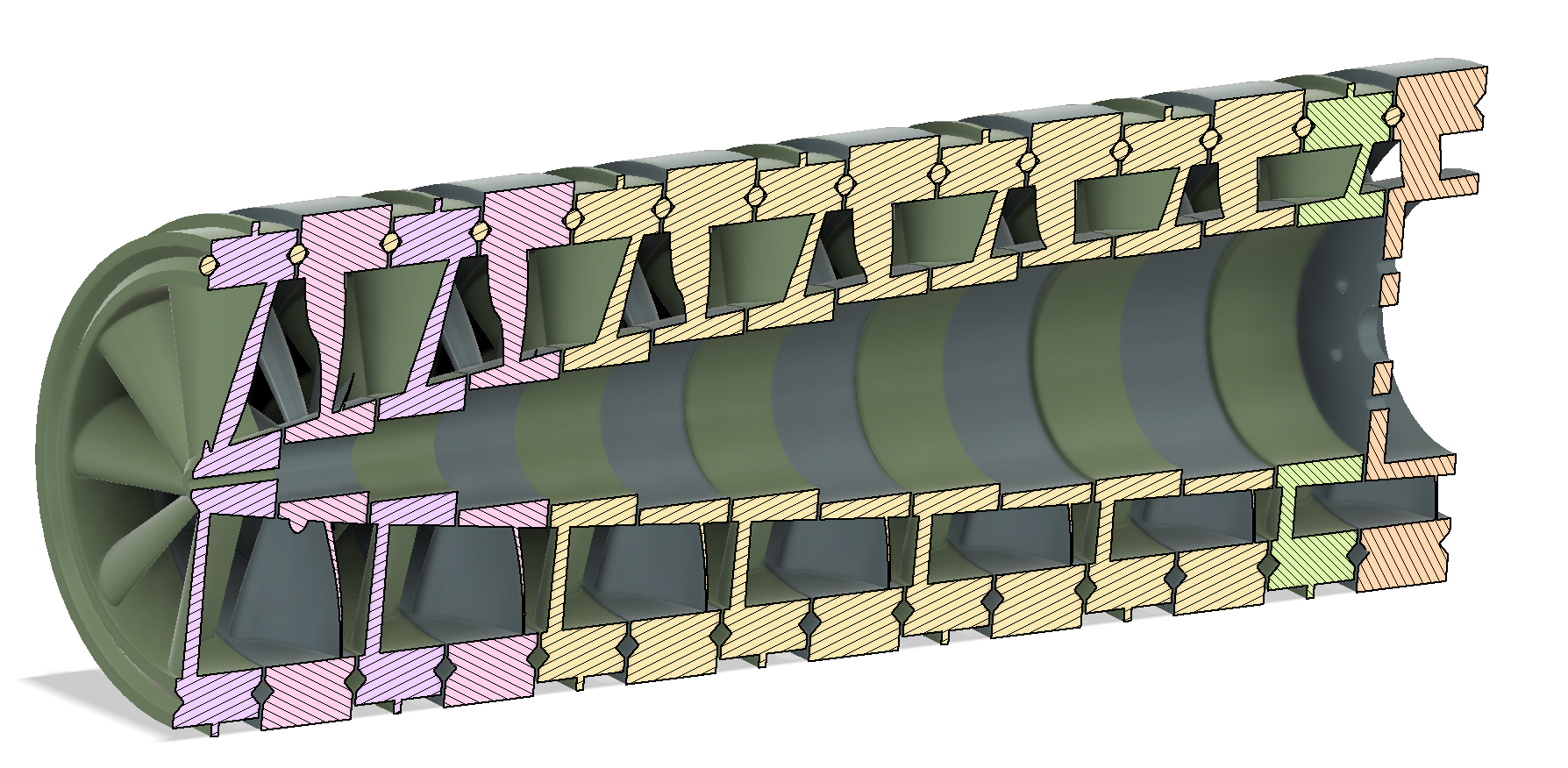
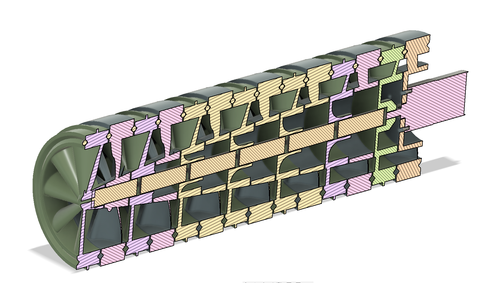
- Modular, axial flow compressor testbed that allows for relatively easy exchange of rotor and stator components to test geometries
- Data outputs
- Pressure measurement(s) - Would be great to find a way to have pressure taps at each stage, but this may not be feasible
- RPMs - Positional measurement, nor direction of rotation are needed, so this can be a pretty simple encoder
- Power Consumption - To ensure this isn't just absurdly wasteful. My expectation is that it will be significantly less energy efficient than my current piston-driven counterpart, but no clue what to expect really. Doesn't seem reasonable to baseline against standard axial flow compressors, since their tolerances, aero-optimisation, and operating regime are just SOOO far from what I will be working with.
- Flow rate - Measure of flow rate out of main tap. Ideally, a very low impedance measurement at the exit valve of the compressor to try to maximize range of pressure to flow rate trade-off.
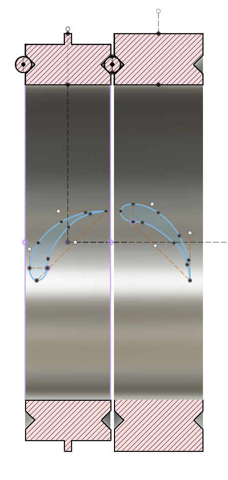
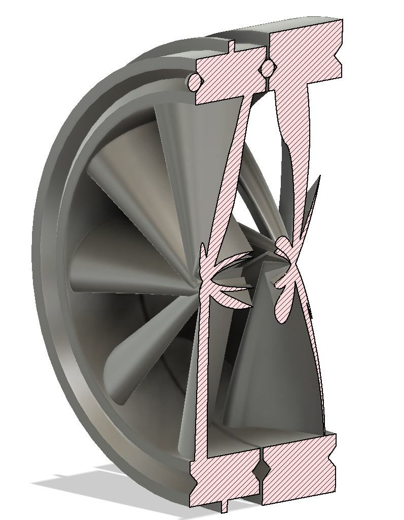
- The main purpose is mechanical. It will be taking the axial loads trying to separate the stages, the torsional loads from the drag on the stators, as well as any radial loads due to balancing and such.
- Sealing. These outer bands will keep the pressure gradiant across the bearings to only be the gradiant between stages, instead of allowing it to vent directly to atmosphere. This should help reduce losses (although surely it won't stop them entirely....assuming I'm lucky enough to get any pressure to build up in this little thing anyway)
- Details
- Parent Category: BubsBuilds Projects
- Category: Tool-related Projects
WIP - PAGE/PROJECT IN THE WORKS - WIP
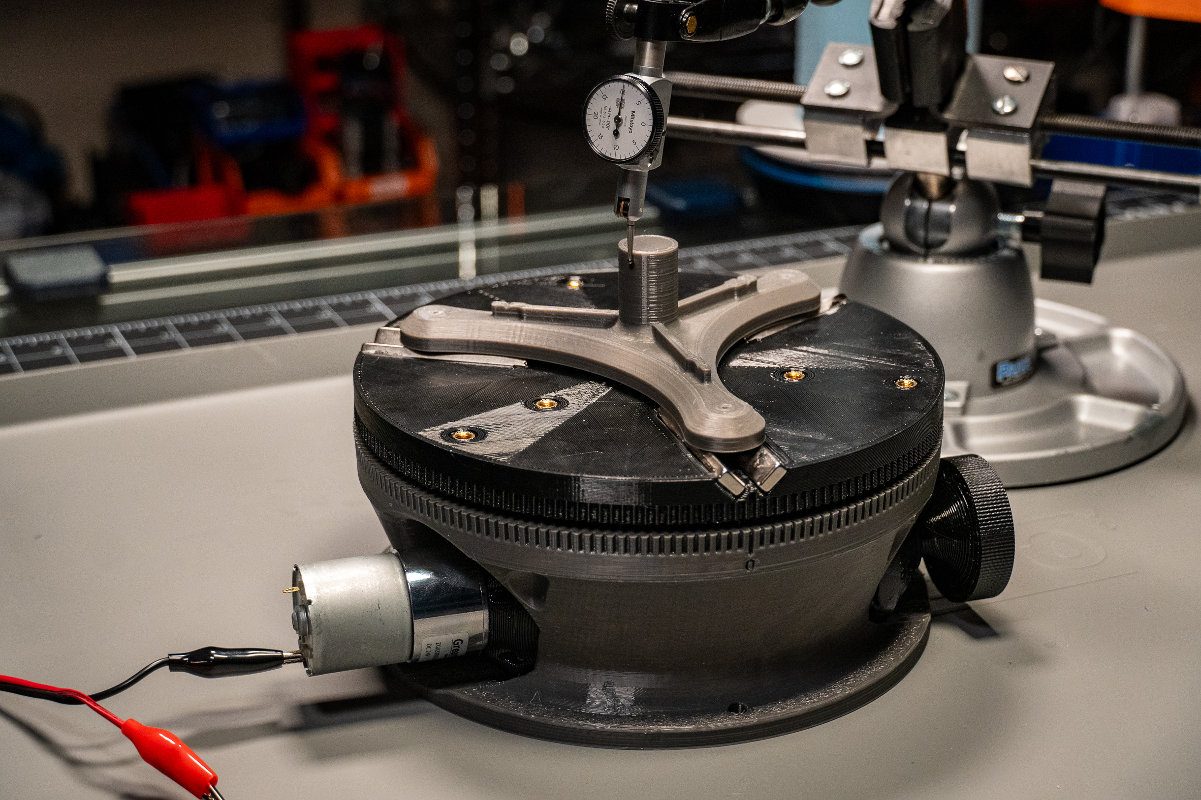
I've come across more than a couple of occassions recently in which I found myself wanting to controllably spin stuff while tinkering on projects. The best tool at my disposal for this task was my "little" 6 inch rotary table for my mill.

While it's certainly up to the task, it's a heavy little bastard! So to keep me from lugging it up and down the stairs from the shop to the 'lab', I decided I should take a stab at a DIY, lighter-duty variant.
Design
OnShape CAD files available to do with as you please here.
I have since moved this project over to Fusion. Only significant difference is the addition of a stepper mount and coupler.
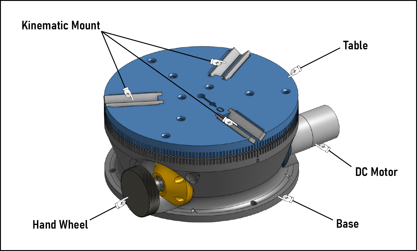
The above image shows the major externally-visible components. The Base is a printed part that provides not only the structural support for loads from all of the other components, but also is responsible for controlling the alignments of the motion components.
On top of the Table is the kinematic mount, formed by bar magnets set at 45 degrees from the table surface (so a 90 deg V.) If you haven't come across this style of interface before, you can find general info if you give a Google to "Maxwell clamp" or "kinematic coupler." I included a very similar coupler on my passive rotary / overkill papertowel holder build , as well as a great many of projects in my day job over the years...they're just tops :) hopefully seeing the repeatability numbers down below will start bringing you around to sharing my fondness for 'em.
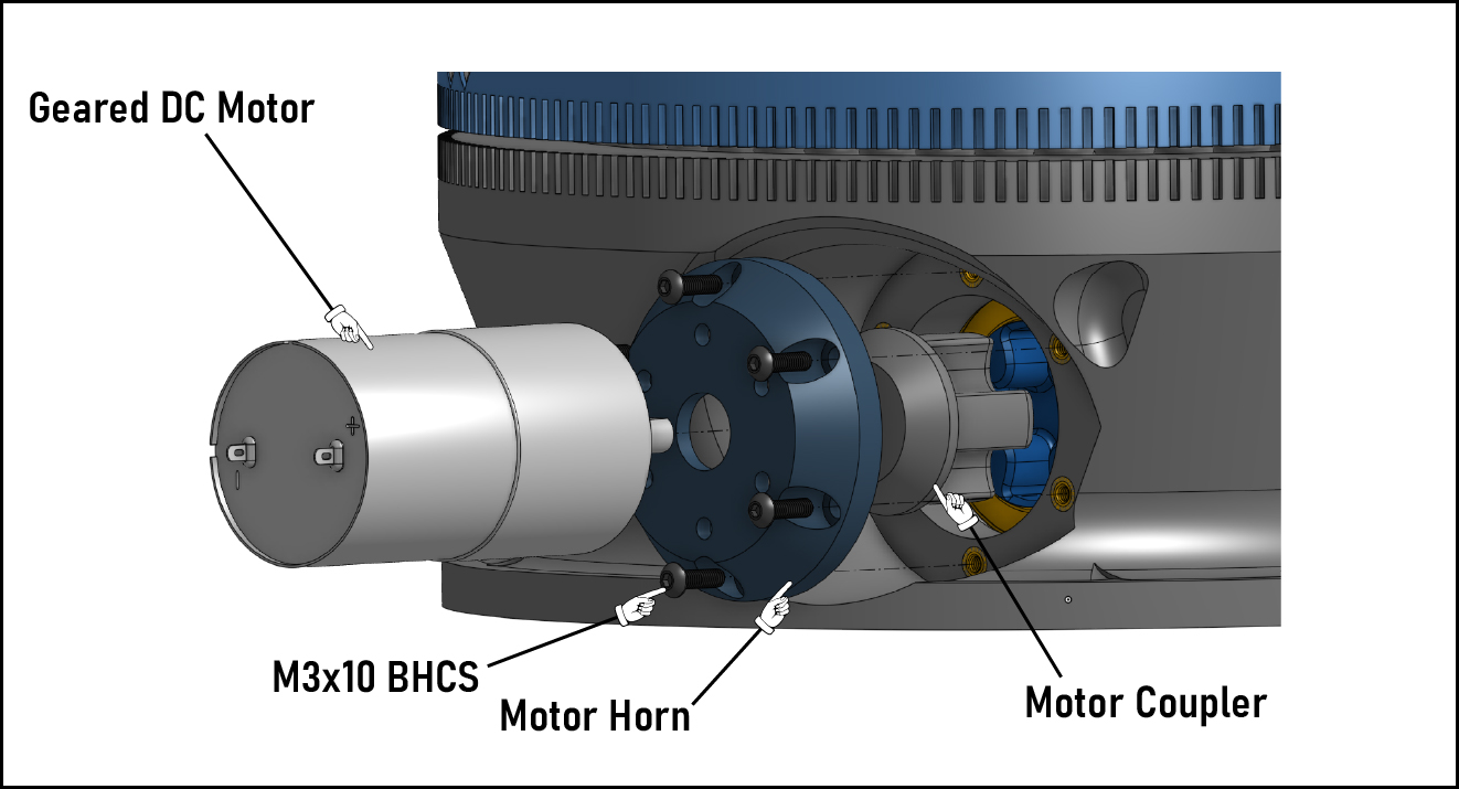
One thing I decided to add that my machining rotary is missing is a power feed! In addition to the hand wheel for manually driving the table, a DC motor can be coupled to the other side of the drive mechanism. There also should be plenty of space to swap out this DC motor for a stepper, should I decide to down the line.
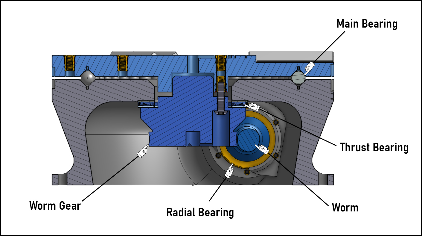
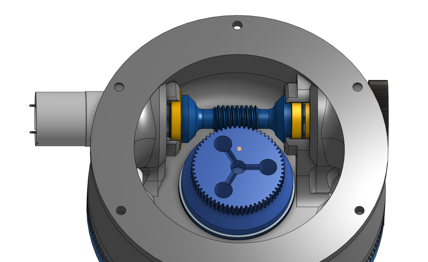
The Table is driven by a worm gear drive housed inside the base, as shown in the below image. The worm gear is integrated into Hub component, which attaches to the Table via three M5 fasteners. Sandwiched between the Hub and Base is a needle thrust bearing. This thrust bearing's counterpart is the main bearing that is integrated into the surfaces of the Base and Table. V-groove channels in the top of the Base and the bottom of the Table form the bearing races, and the rolling elements are 9.5mm steel balls (aka 3/8 inch slingshot ammo....hey, it's quite round and damn cheap).
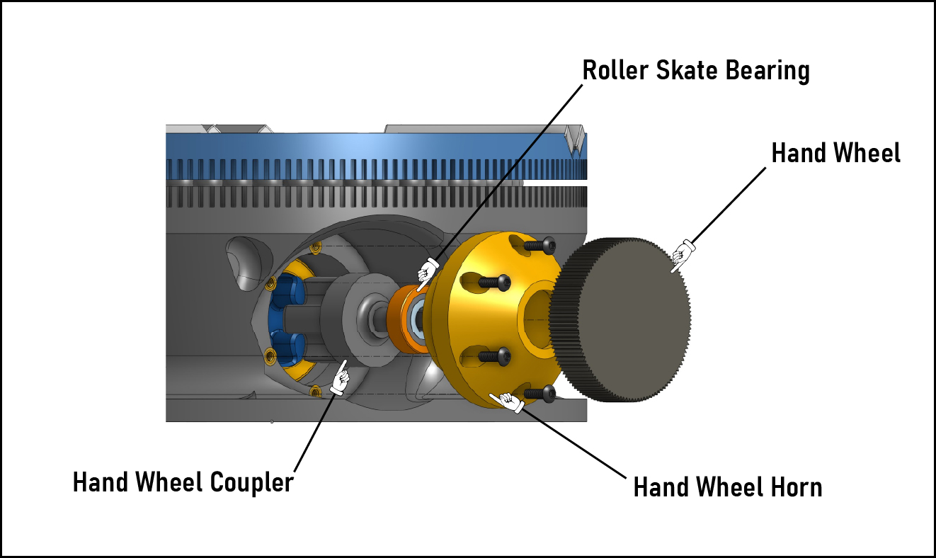
On the hand crank side of the table, a printed coupler sits inside the "hand wheel horn", held in place with a roller skate bearing (I used these. They're overkill for this, but they run really smooth.) The hand wheel presses onto the coupler with a light interference fit. It's really just intended as a close running fit, but with 3d printed parts it ends up being more like a bit of an interference fit.
On the power feed side is a similar printed coupler, but with a d-hub hole for engaging the motor shaft and no support bearing (the motor has a bushing that's serving the same purpose.) For a motor, I'm using one of these 24VDC, 150RPM motors. Something a little faster might be nice, but I might worry about the wear on the worm. Plus I don't really need this thing to be speed demon, so I don't have any plans to swap it.
Build
BOM
- Printed Parts
- Base - Polymaker PETG
- Table - Polymaker PETG
- Hub - Siraya Tech Fast ABS-Like Resin
- Worm - Siraya Tech Fast ABS-Like Resin
- Hand Wheel Horn - Polymaker PETG
- Motor Horn - Polymaker PETG
- Hand Wheel Coupler - Polymaker PETG
- Motor Coupler - Polymaker PETG
- COTS
- (49) 9.5mm Steel balls - I use these quite a bit, so I just buy these big tubs :)
- (2) 6806-2RS Roller Bearings - 30x42x7mm
- (1) AXK5578 Thrust Bearing - 55x78x3mm
- (1) 12V or 24V DC Motor - 12V is probably plenty and may be easier to power depending on what ya have available.
- (1) 608-2RS Roller Bearing (aka Skate bearing) - I've built them with both these and these. The latter feel better, but the former are cheaper and do the trick.
- (12) M3 Heat sets
- (13) M5 Heat sets
- (6) 60x10x5mm Bar Magnets
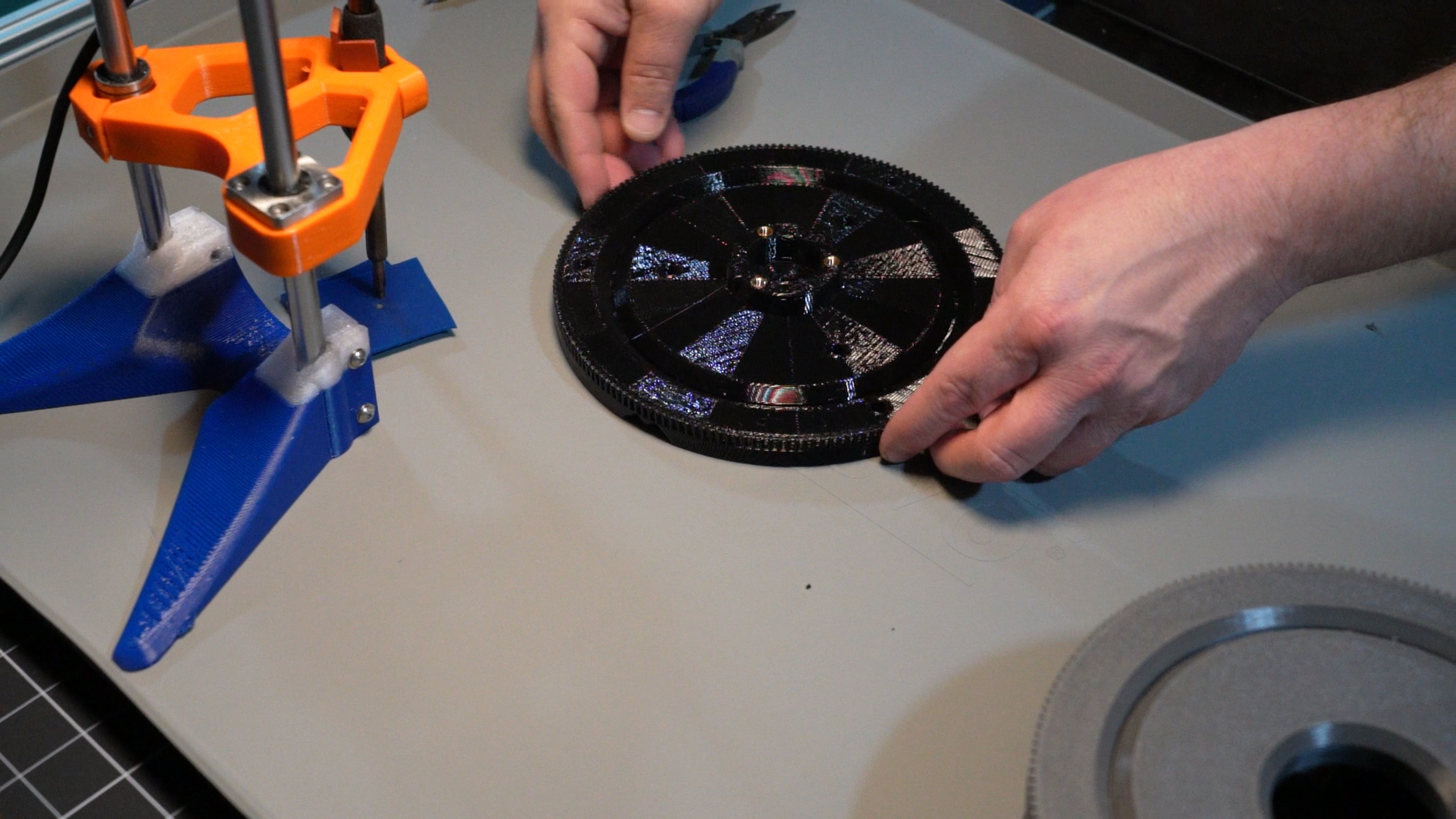
I started out by printing out all of my parts. For the version I showed in my YouTube video, I printed everything except for the worm and worm gear from PETG with FDM. For the worm and worm gear, I printed them from an ABS-like resin to get better stiffness and smoother gears.
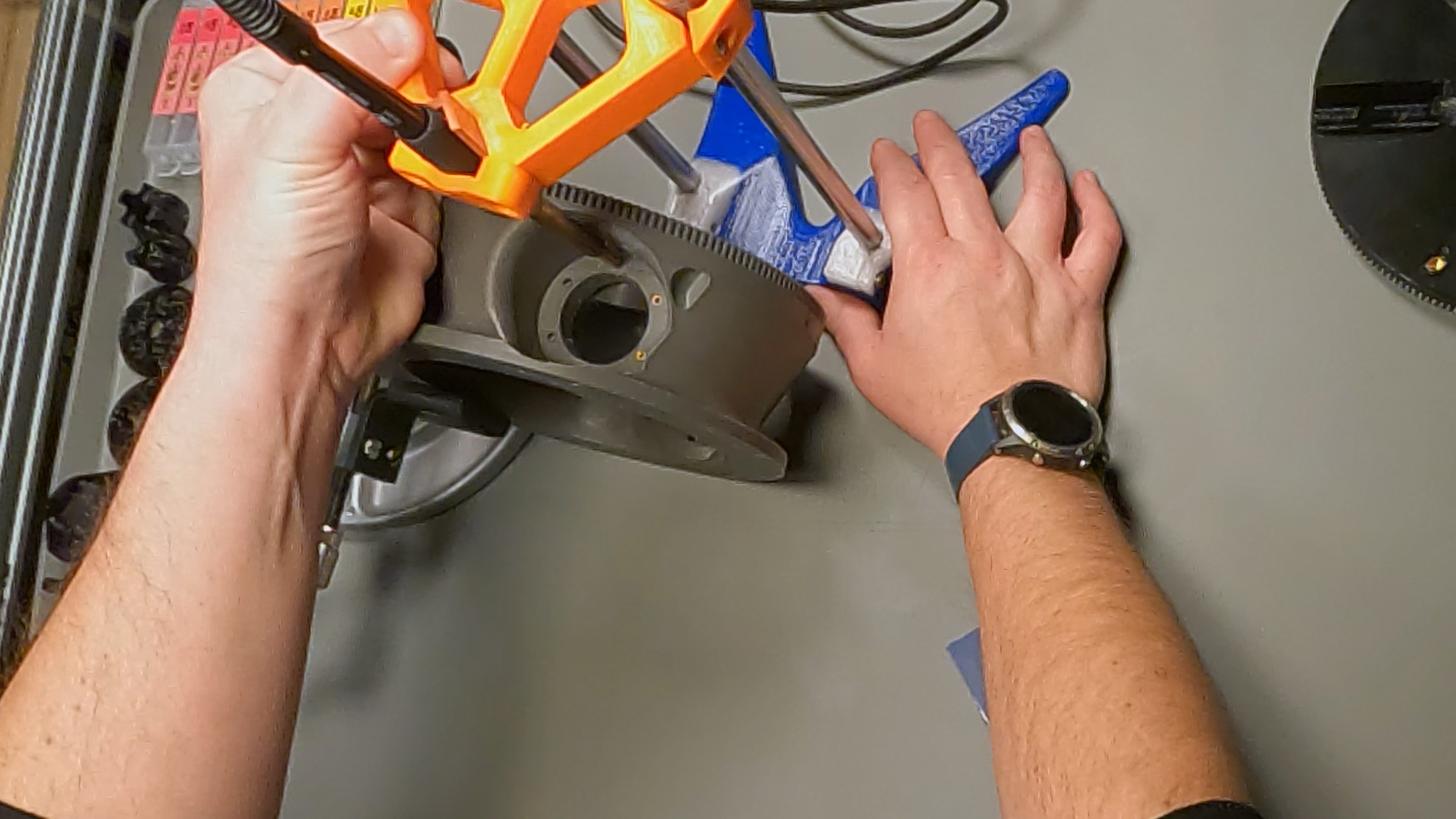
I then put in the M5 heat sets in both the top and bottom of the Table.
For the ones in the top surface, I just set the table into the base so it wouldn't wobble on the table.
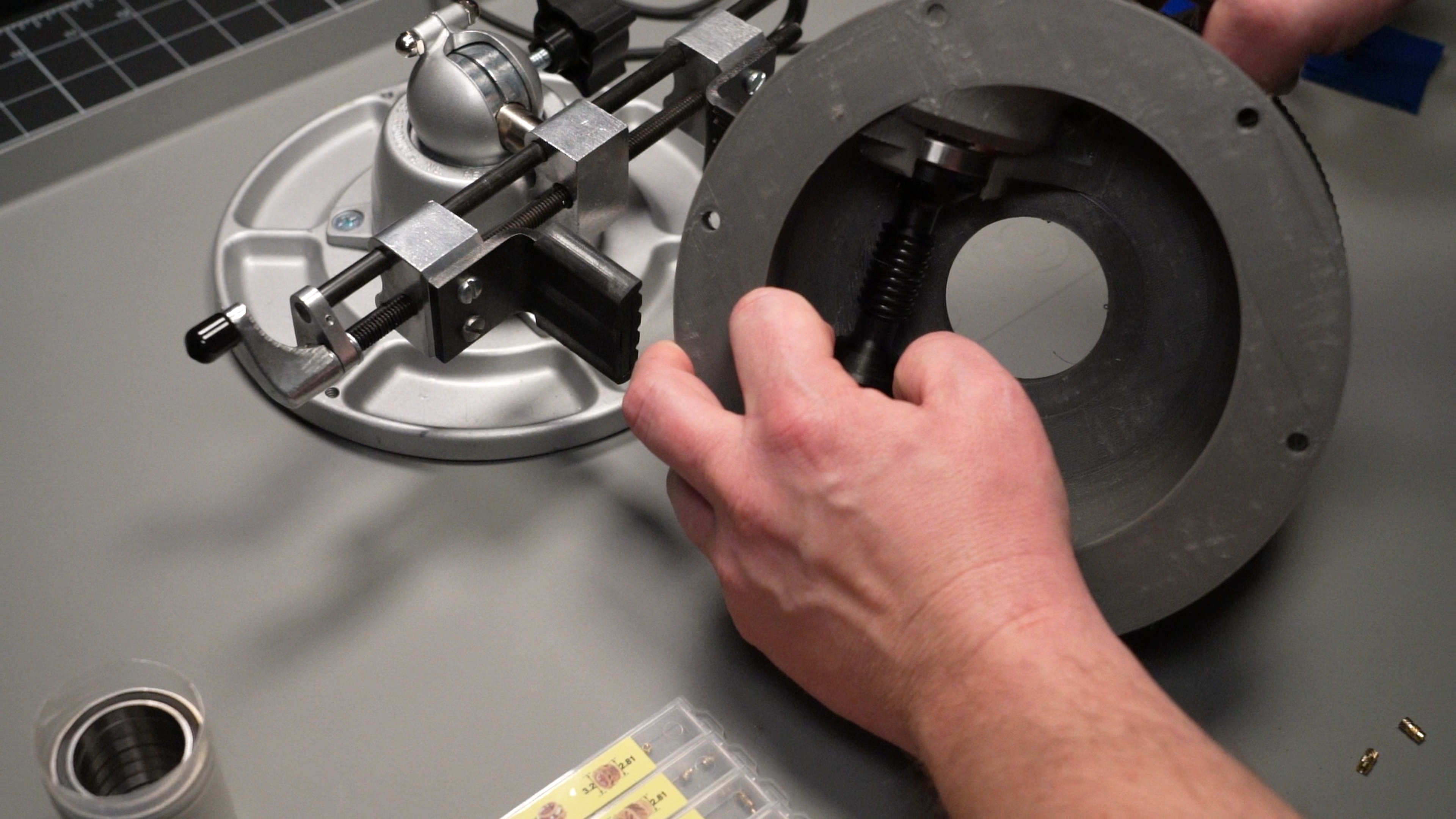
Next, I put the 6 M3 heat sets into the mount on the narrower diameter drive mount. I wanted to insert the worm and it's bearings before putting in the heatsets on the wider side, because the bearing needs to pass through that opening and I didn't want to risk having the heat set bulge the melted material into that opening.
After those 6 heat sets were in, I put the large aperture roller bearings onto the ends of the worm, and slid that sub assembly into place.
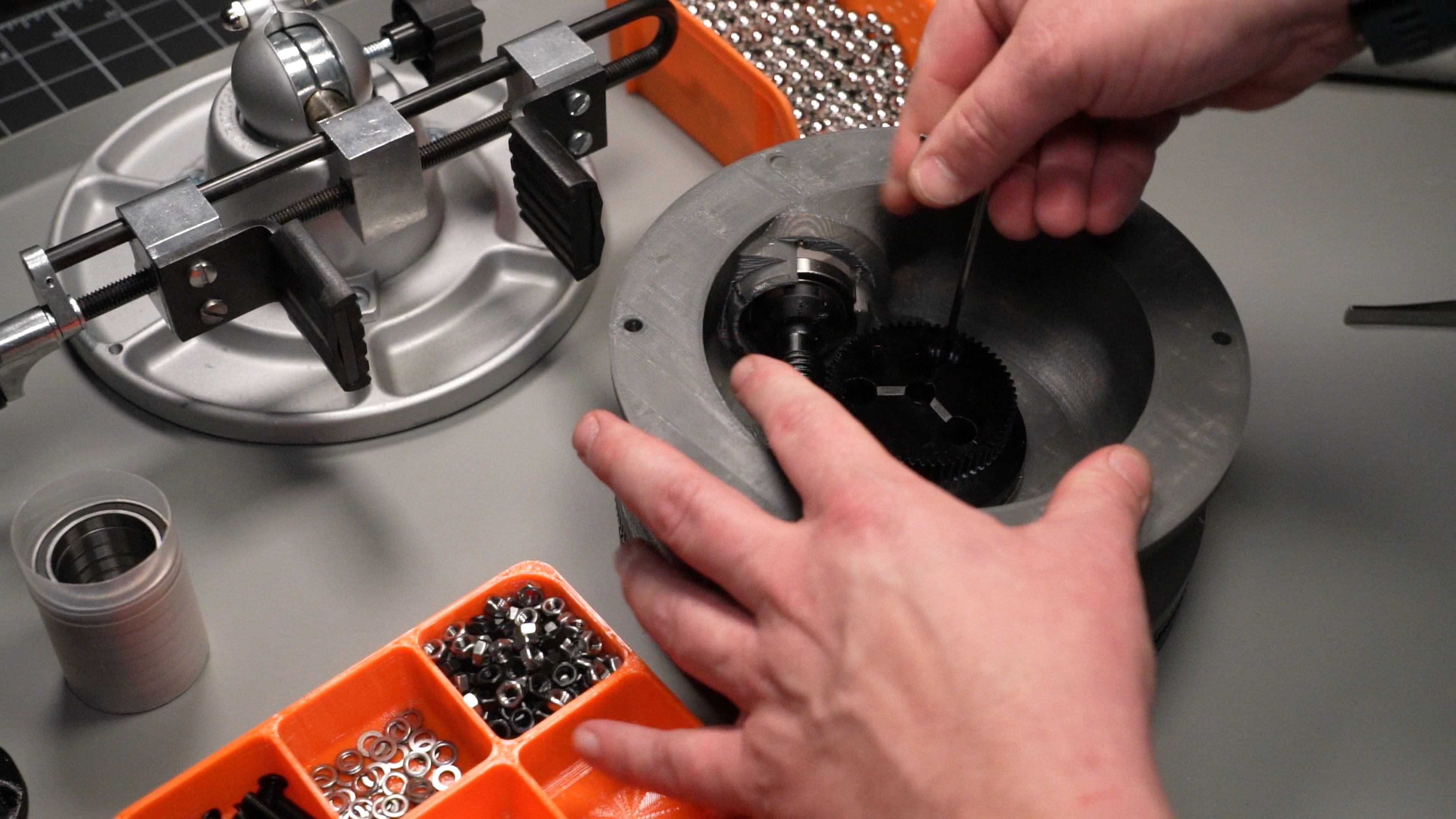
With the worm bearings seated, I put in the heat sets on the other drive mount.
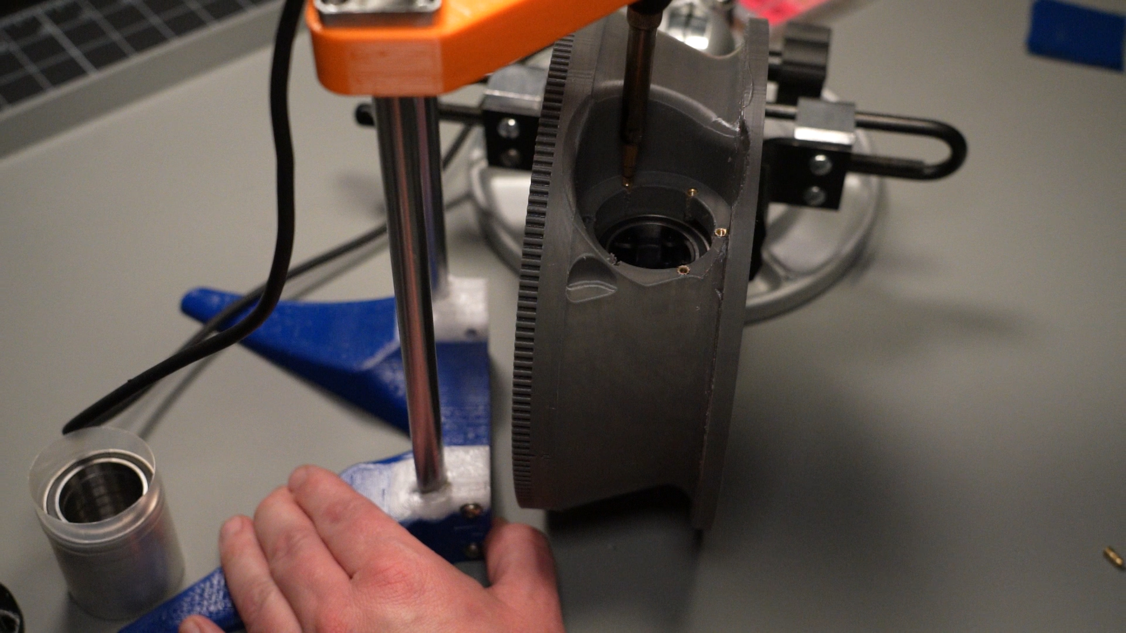
I then poppoed the thrust bearing into place, inserted the worm gear, and secured it to the table using 3 BHCS M5s.
Measuring runout:
Just for the sake of making sure there's no uncertainty with what I mean by runout, allow me to elaborate...probably to much. Feel free to skim. When I say, "runout", what I I'm referring to is any movement of the Table, relative to the Base, other than the desired spinny bit. There are three types of runout that I want to measure on my rotary table:
Radial Runout

Axial Runout
Axial runout is error motion that is along the axis of rotation, or 'up and down' as I'd probably refer to it if just pointing at it and talking ¯\_(ツ)_/¯. But hey, in good news, my gif-making skills definitely improved a bit for this one. So by Axial I bet it's gonna be fuckin epic.

Angular Runout

Measurement Setups
In order to obtain the measurements I'm after, it will require nine sets of measurements. Each set of measurements will include measurements recorded at consistent intervals throughout the 360 degree travel of the table. So why nine? What seem like an extra six will (hopefully) make a bit more sense shortly, but they're going to help us make sure we're measuring our actual motion and not the surface/shape of the surface we're measuring.
The nine measurements will require the indicator/sensor being mounted in three positions. Or, if you're flush with cash, just get yourself three sensors and a nice frame for em...while you're at it, send me a set too :)
Position 1 - Low on the post, near to the mount face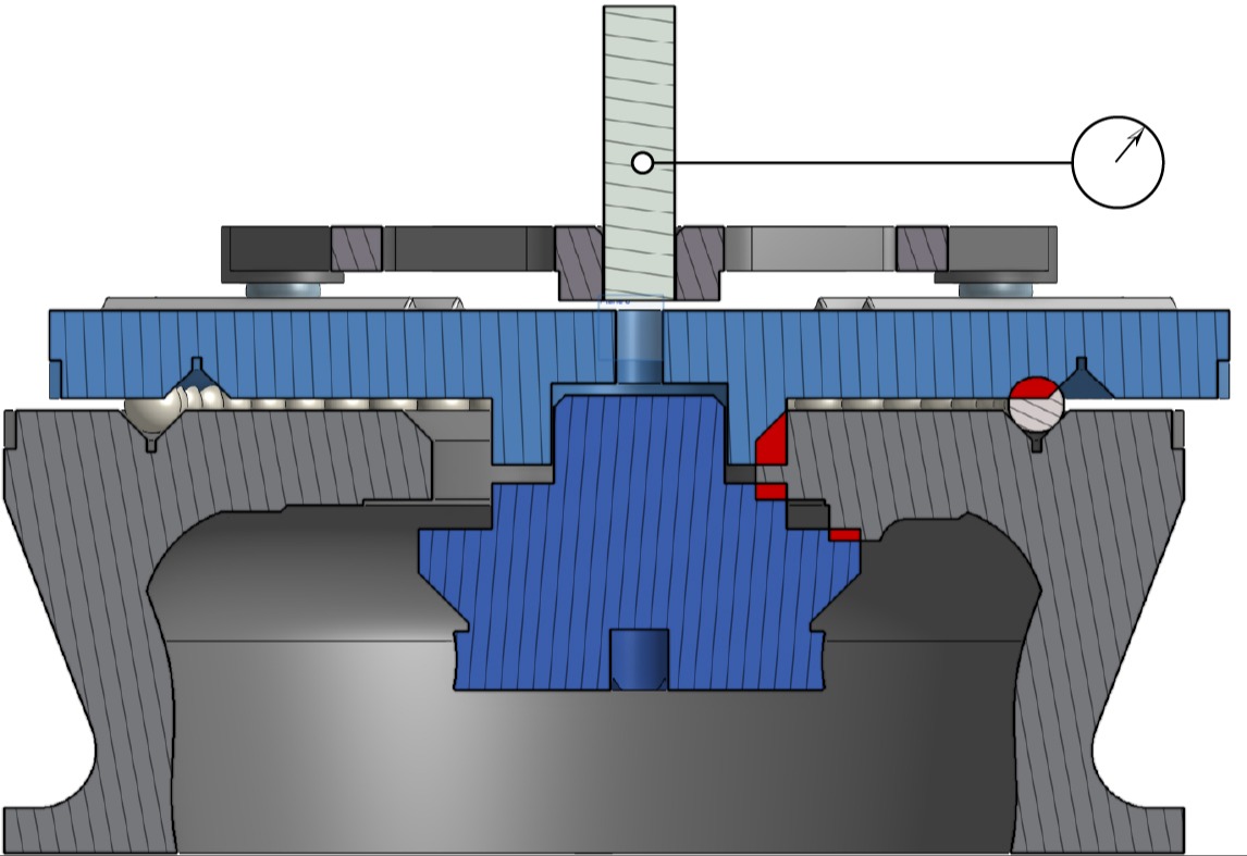
Position 2 - 50mm up the shaft from Position 1
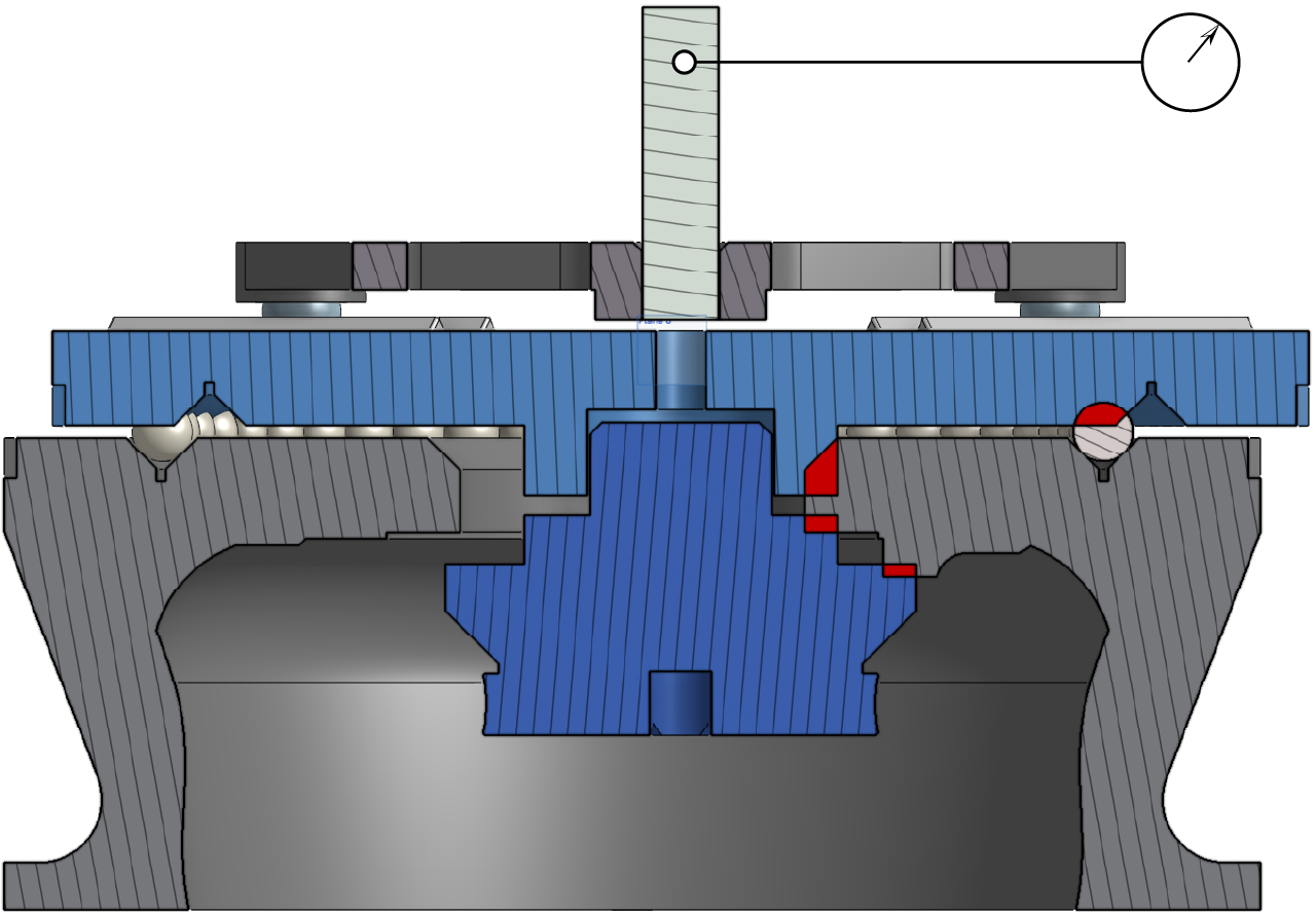
Position 3 - On top and centered on end of rod.

The remaining six measurements, are repeats of these positions at each position of the kinematic mount. I'm using the kinematic mount here to perform a variation on the "reversal technique" to cancel out part geometry. If you aren't familiar, but are interested, or just want to see if I'm totally bullshitting you, you can find plenty of info out there by giving something like, "reversal technique metrology". The kinematic mount allows us to repeatably position the test sample at 120 degree offsets. I'll show below in the data analysis how I then used these offset datasets.
Mount Repeatability

WIP - PAGE/PROJECT IN THE WORKS - WIP