I frequently run into situations when working on things in the lab (aka my basement) where I want/need compressed air. But I've long hated the heart stress testing that is the standard compressor starting up. I've considered things like putting the compressor in a shed and plumbing air to the shop and lab (garage and basement, respectively :) .) Or building an enclosure that could isolate the noise and vibration, while still managing the heat and air intake.
The main use cases that I currently have in mind are 1) cleaning/drying resin parts after wash and 2) air bearings. The first does not need a ton of pressure, but does love some flow rate. Currently I'm using an airbrush compressor that tops out at around 30psi, and no clue on the flow rate. The latter would ideally have very low flow, and high pressure, but because the air bearings in question are largely experimental and 3d printed....kinda would love both :) But I think if I could supply 50+ psi at a couple cfm it would be enough for testing purposes.
But I've also been kinda kickin around an idea for a continuous-operation compressor that may not be quiet, per se, but should be much quieter than my current options. The article title kind of gives it away, but the idea is based on the axial flow compressor stages in a jet engine. So basically just try to duplicate(ish) the left half of the below (although I just noticed that their sketch is missing the stator blades...so pretend those are there too.)

Objectives
Ultimately, what I'd like from this compressor is the ability to provide 50+ psi at a flow rate of at least 3 scfm. But in the shorter term, I'm just curious if a 3d printed (or mostly) axial flow compressor can achieve any meaningful pressure increase at all.
So objectives for this concept tester are:
- Modular, axial flow compressor testbed that allows for relatively easy exchange of rotor and stator components to test geometries
- Data outputs
- Pressure measurement(s) - Would be great to find a way to have pressure taps at each stage, but this may not be feasible
- RPMs - Positional measurement, nor direction of rotation are needed, so this can be a pretty simple encoder
- Power Consumption - To ensure this isn't just absurdly wasteful. My expectation is that it will be significantly less energy efficient than my current piston-driven counterpart, but no clue what to expect really. Doesn't seem reasonable to baseline against standard axial flow compressors, since their tolerances, aero-optimisation, and operating regime are just SOOO far from what I will be working with.
- Flow rate - Measure of flow rate out of main tap. Ideally, a very low impedance measurement at the exit valve of the compressor to try to maximize range of pressure to flow rate trade-off.
Design Notes
2024/02/10 - First pass
Starting out with trying to make a basic (although I'm sure extremely inefficient) airfoil.
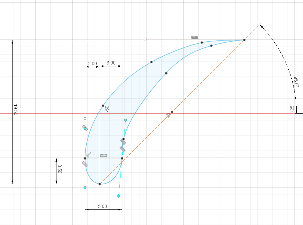
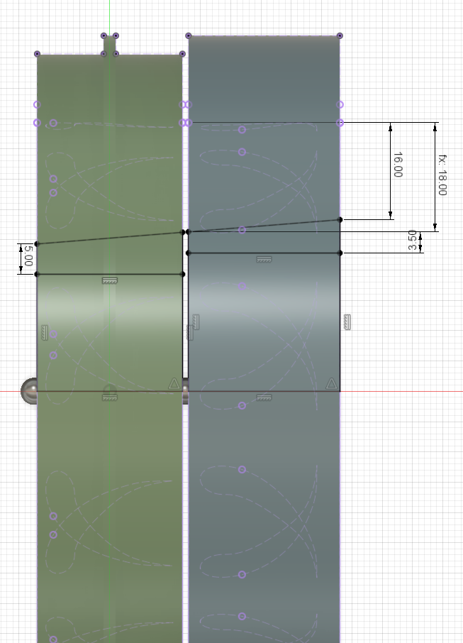
My plan for the first iteration is to use my trusty print-in bearings, with BBs (4.5mm steel balls) as the rolling elements. The rotors will be fixed to the bearing at the OD, instead of the traditional ID hub. So the bearings will be around the perimeter, with one race of each bearing being in a rotor, and the other in a stator. The below shows the sketch cross-section I've got as a first pass, although these may change as I try to actually make this thing 3d :) I think a big perk of going with this style of bearing arrangement for this project is that the gap between the rotors and stators will be set at each bearing, and so won't be subject to stackup through the system.
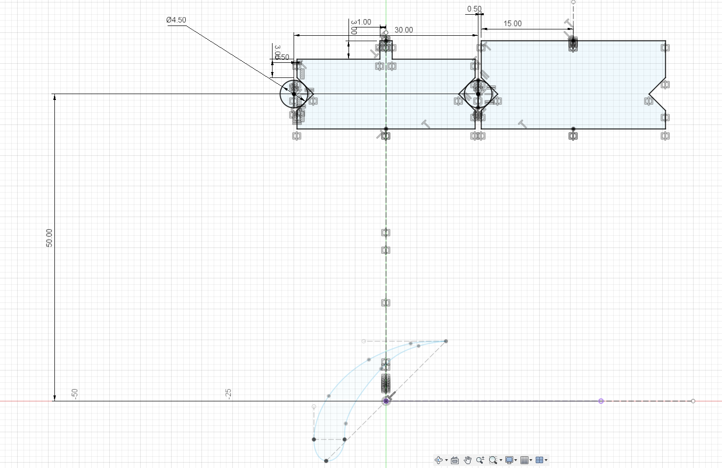
I realized I probably should have gone ahead and included the stator in the initial sketch. I am definitely swaggin it here, so I just copied the rotor airfoil and positioned it in a relative location that...looks reasonable
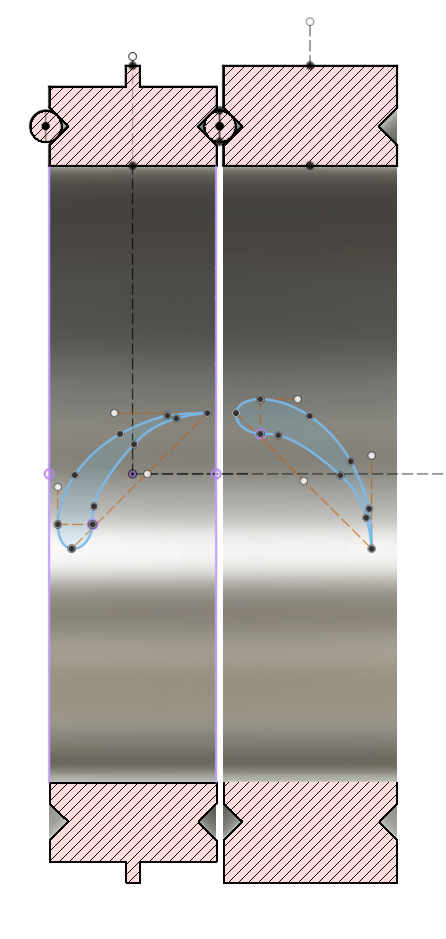
Revolving those, hopefully it makes it a little easier to see what I'm goin for here. The left side will be the rotor, and the right the stator. The little tab at the top of the rotor ring is intended to offer the option to put an encoder on it, but that doesn't make sense on all rotor stages, so I may revise that. My plan is to have the stators rigidly fixed to each other with bands around the exterior to :
- The main purpose is mechanical. It will be taking the axial loads trying to separate the stages, the torsional loads from the drag on the stators, as well as any radial loads due to balancing and such.
- Sealing. These outer bands will keep the pressure gradiant across the bearings to only be the gradiant between stages, instead of allowing it to vent directly to atmosphere. This should help reduce losses (although surely it won't stop them entirely....assuming I'm lucky enough to get any pressure to build up in this little thing anyway)
Random thought, but I wonder if it might be worthwhile to try putting a standard PC box fan on the intake of this thing. They are quite good at providing air flow and maybe having this as a feeder to the first stage would be worthwhile...somethin to consider if it seems like it's being starved at the inlet (which is something I'm a smidge concerned about.)
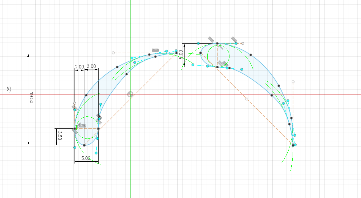
Ok, so back on track. I struggled with the Fusion360 Project on surface feature for quite a while and decided to give up and go cludge. The only real issue is that now I have little bits of blade sitting in the V groove. But I'll just do a subtract revolve at the end to clean it up. Not ideal, but it'll do. In hopes of helping to improve packing, I made a smaller, higher angle of attack sketch of a similar airfoil shape, and then just lofted the larger one to the smaller for both Rotor and Stator.
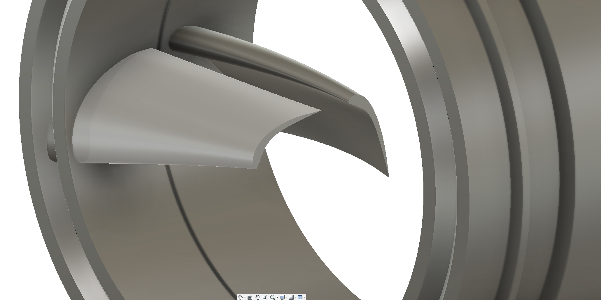
Ok....I'm officially excited....
No clue if this thing will work, but I already love how it looks...my bar, she's low.
Ok, got the Vs cleaned up. I'm going to consider these kind of the base 'unit cells' for all of the stages. The tangled mess in the middle will be replaced by either the hub on the rotor or an aperture on the stator. The stages will need to have a progression in the diameters of both of these along the direction of flow. My hunch is that this change in diameter is going to be the main thing I'm going to need to tweak down the line.
I am far from a fluids person (as you have probably already seen clearly from my approach to airfoil 'design' :) ), but my fear is that since I don't really have any idea what kind of pressure ratio I might be able to get across a stage, I suspect I'm going to get the compression in the volume wrong and stall the flow...I think that's a thing...right? While I'm speculating, the other parameter I'm already thinking about wanting some flexibility in is the attack angle of the stators. I'm wondering if I could figure out a not-too-complex option for getting some ability to adjust this...but, that's for a future rev (if ever).
Time to start crackin on some first attempt stages!
Since I'm building off of the Final stage, and since I should be able to stack any number of stages, I'm going to use "fs-#" as the naming scheme for the stages. So the final stage, with the motor attached is fs-0, the one right before that is fs-1, etc.
Starting at fs-3, I'm switching to a slope of 2mm per stage.
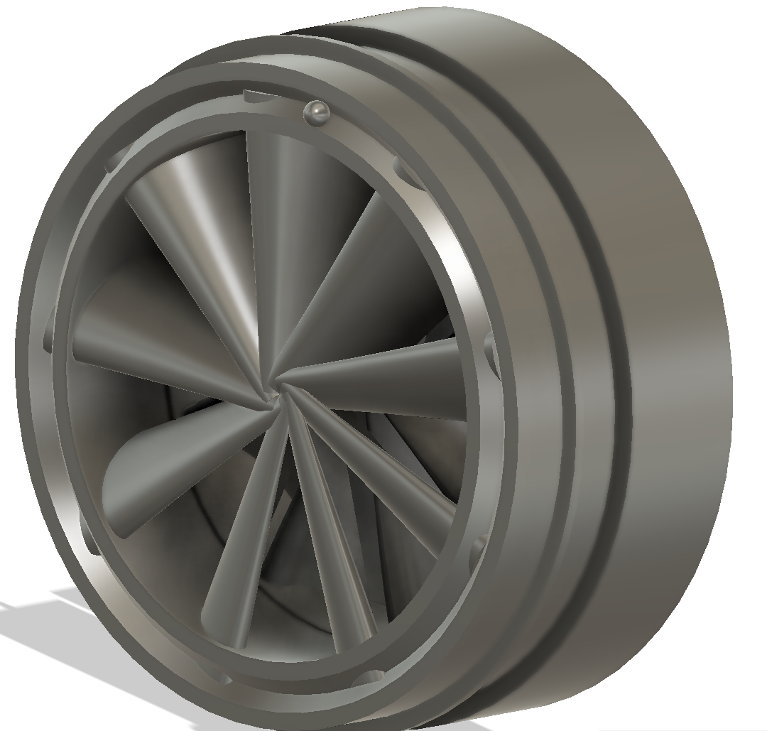
Alright, I tossed fs-0 through fs-4 into an assembly even though they're still incomplete....I'm impatient and thought it was gonna look cool... I wasn't dissappointed
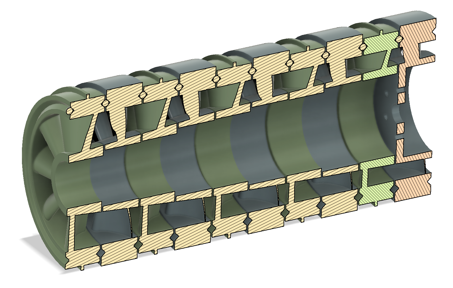
The stairstepping along the inner diameters inside the hubs throws off the look a little, but that isn't in the flow and I still need to add the couplings/hubs to the rotors...in hindsight, that would have been smart to do before making the other parts....oh well, I'm gonna make the rest and close it ¯\_(ツ)_/¯
I'm also going to increase the pitch again to 3mm per stage starting at fs-5.
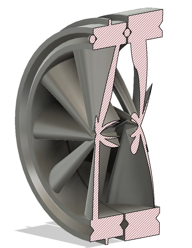
And with that, this config seems to run out of room at fs-6.
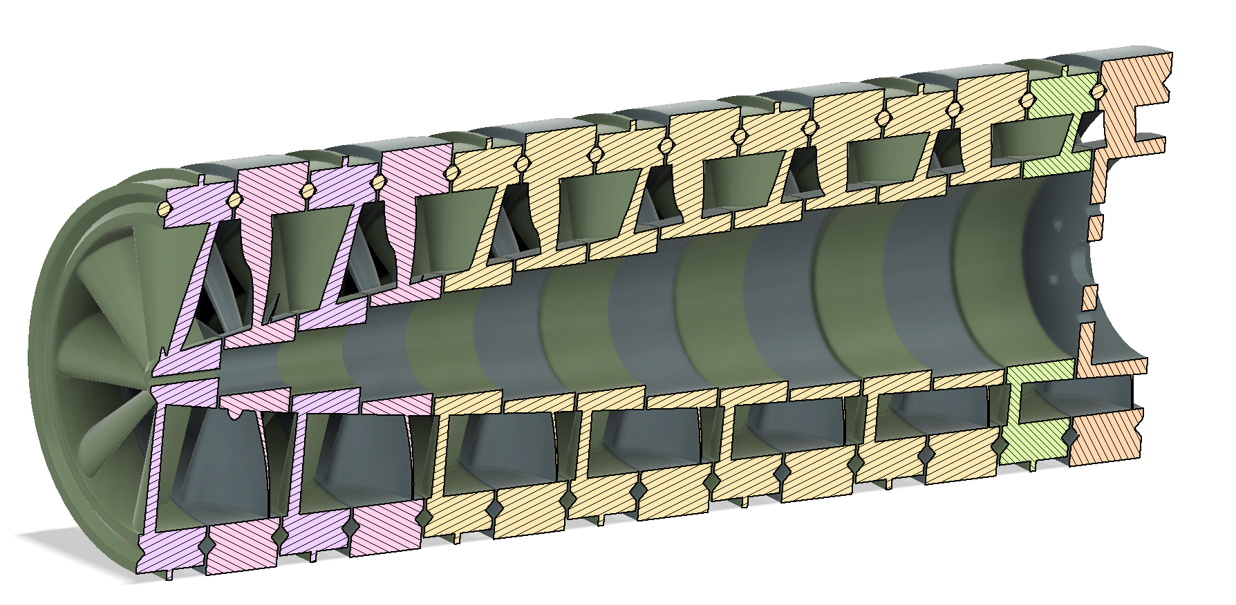
The total length is a little over 350mm
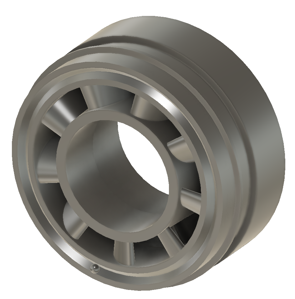
It's gettin late, and I'm runnin out of words...you're welcome, but I got a first pass at the hubs and simple linkages.
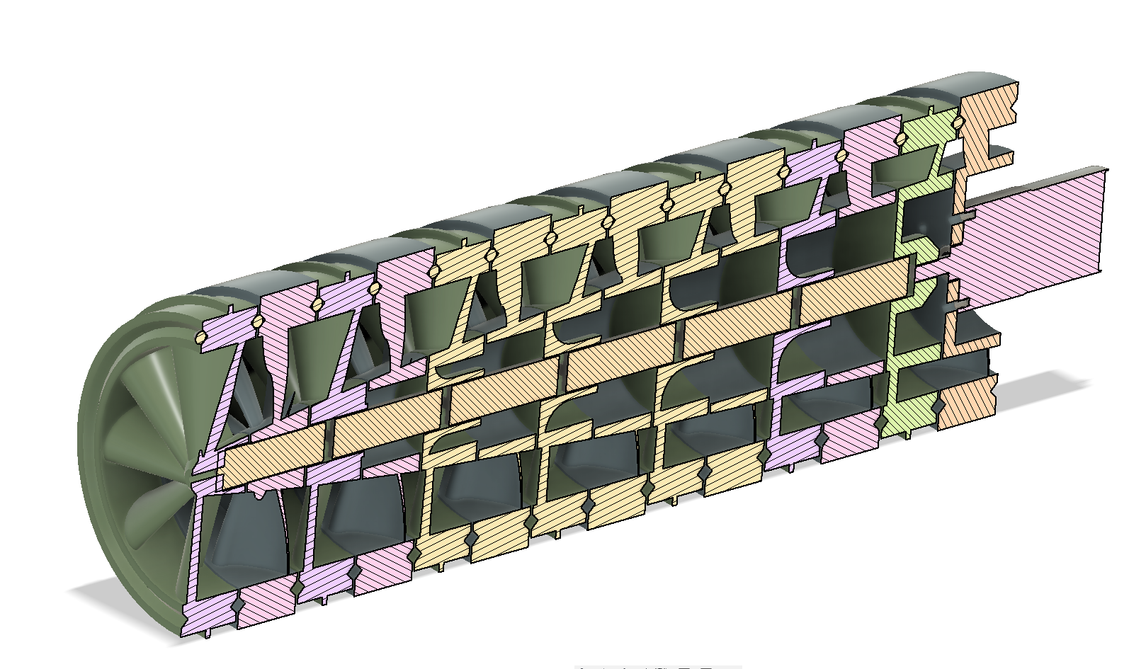
The hubs just have a "+" shaped cutout, and the linkages are matching extrusions with relatively loose running fits. The thought is, all I need is to transfer the torque, I don't really care about backlash, etc. (I don't think). And the fastest motor I have in this form factor is 550 RPM, so I don't expect balance issues to be too significant.
The next thing I'll need to do is add the structural elements to hold it all together, but that's gonna have to wait for tomorrow.