For a handful of recent projects, I've had the want/need to take some displacement measurements for things like lookiing at the runout in some 3d printed bearings (like in my recent Rotary Table build.) I had some dial indicators for my mill that have done the trick thus far, but none of my indicators are digital and I'd really like to be able to record data. So I decided to put together a little digital displacement sensor using some opto-interrupters I have on hand.
After calibrating and some intial testing, I'd say it's good to somewhere in the neighborhood of 10 microns over a measurement range of about 0.6mm. Not the most impressive dynamic range of any sensor I've encountered, but not too shabby for under $10!
Build
BOM
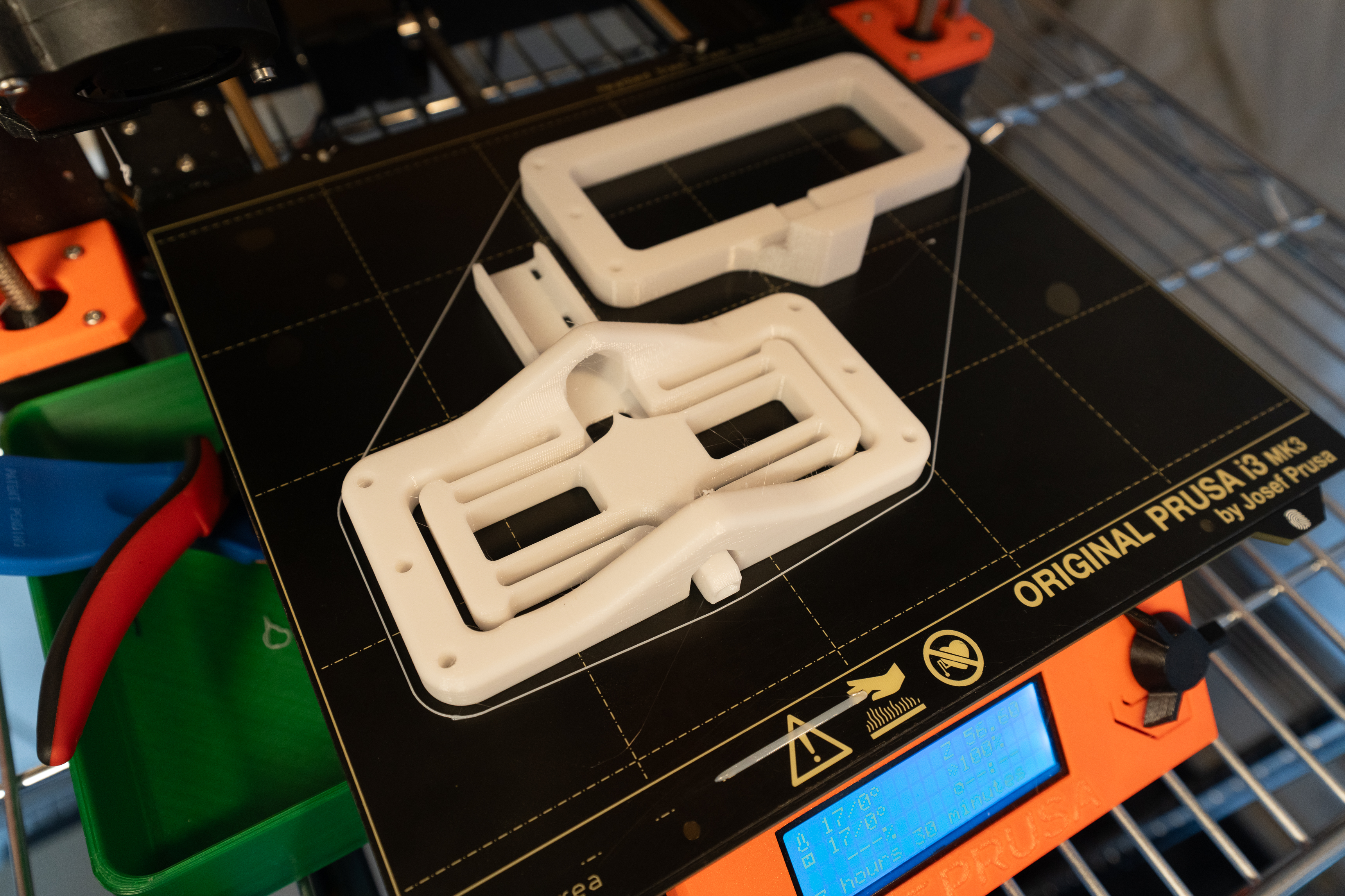
- Printed Parts:
- FlexureFrame_BuiltInBlade
- CalFrame - If you plan to calibrate similar to how I do below
- COTS
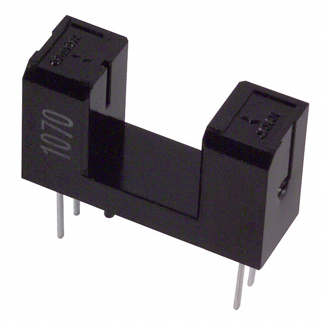
- EE-SX1070 - OptoInterrupter
- 4.5mm Steel Ball - aka a bb. This is your stylus tip. Anything hard, spherical, and around this diameter should work. I've been using these, partly for the hard anodized finish...no clue what the other part was :) but they've worked for me as styli and in bearings and such just peachy.
- Glue - I recommend super glue of your favorite variety. I used this medium viscosity stuff.
- Resistors - I used one 180 Ohm and one 4.7 kOhm
- Wire - I used some old scrap telephone wire
- Attach wire leads to the optointerrupter. I usually crimp on Molex female connector pins onto the ends of the wires. I then slide these on to the pins of the opto and then solder them secure. If you have a more elegant solution that you like, I'd love to hear about it in the comments, but this works well enough.
- Assemble the circuit (see Electrical section below for how I went about this one)
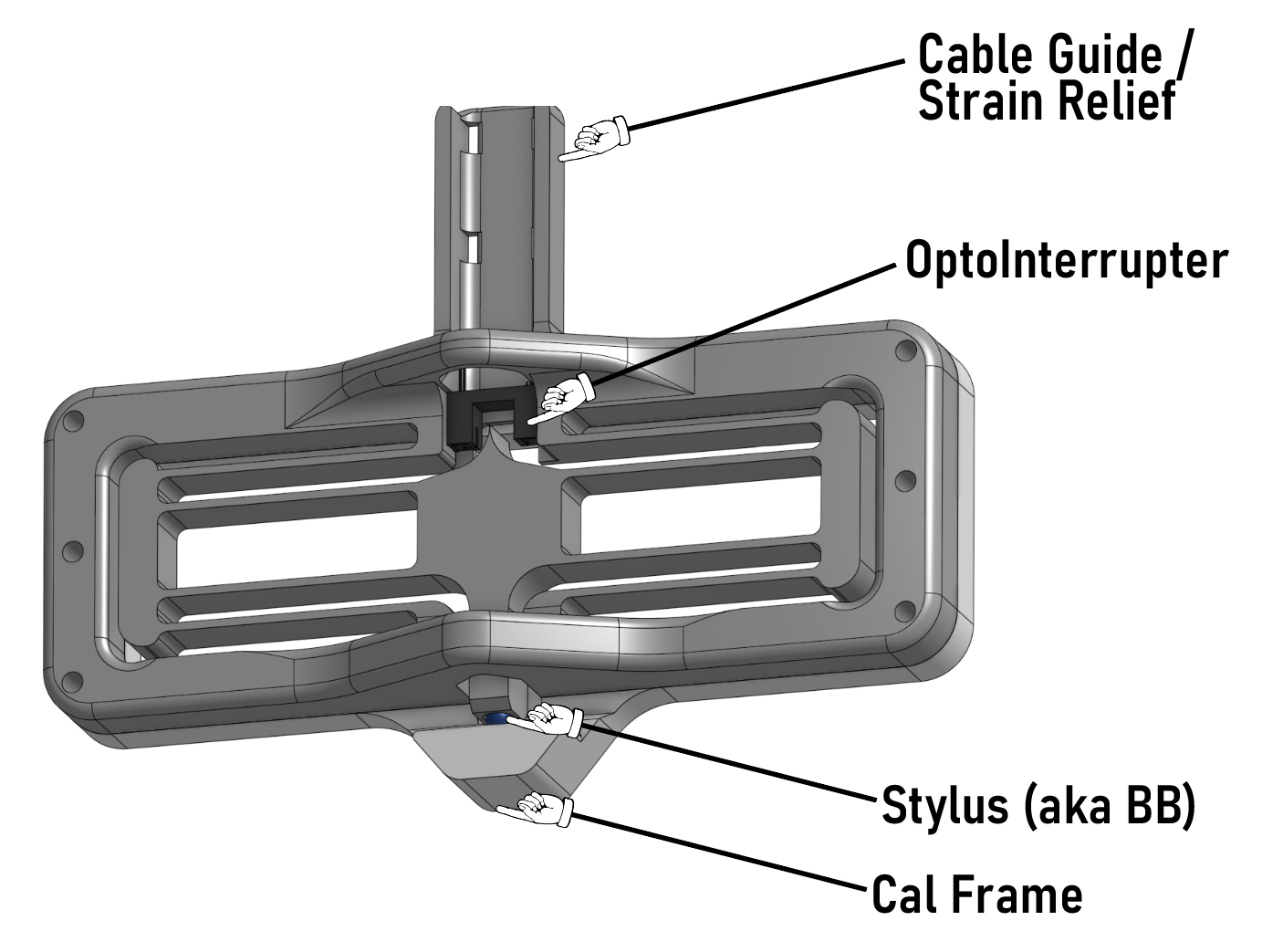
- Feed the wire leads through the arch above where the opto sits in the frame. Feed them all the way through so that the opto is approximately in the right spot. You'll set it's final spot shortly. Also, there are two sets of openings in the Cable Guide for zip ties to provide some strain relief. I like to go ahead and put the zip ties in at this step, but leave them as just loose loops. Waiting to tighten them once the glue has fully set after step 6.
- Connect the wire leads to their appropriate connections on the circuit, and power on the circuit.
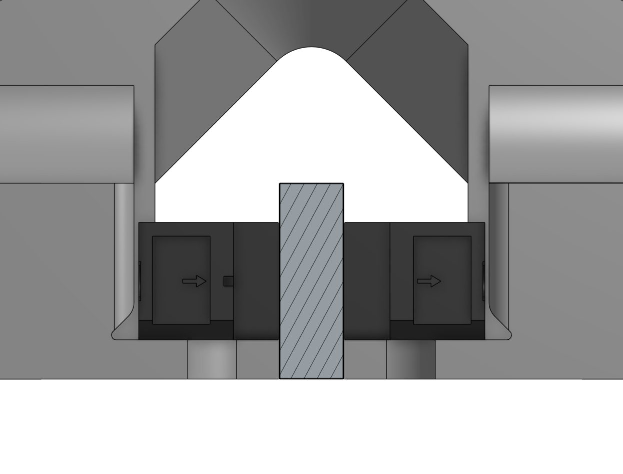
- Hold the opto so that the bottom side of it's U shape is pressed against the plane behind it, and slide it until the output voltage is ~5-10% below the voltage with nothing disrupting the beam. Make sure there is nothing causing the flexure to be deformed while setting this. The goal is to position it such that the plastic 'blade', is inside the measurement range at no displacement. The 5-10% is to try to get away from the highly nonlinear response expected at the ends of travel.
- Once the sensor is positioned to your liking, apply a small drop of glue between the side of the opto and the printed plastic wall next to it. I like to glue one side while using my hand to keep pressure on the other side. Once that side has set (30 seconds or so) I repeat it on the other side.
- Tighten the zip ties in the Cable Guide. Be careful to make sure you don't put a strain between the zip tie and opto. The goal of these zip ties is to isolate the sensor from any downstream tugs, bends, etc.
- Put a small drop of glue in the cone for the stylus, and apply some pressure to the stylus/ball while the glue sets. Don't push too hard, and preferably provide some support so you aren't just pressing against the flexure.
That's it for assembly of the sensor. If you will be using the Cal Frame, it just needs four, M3 heat sets (six if you so desire, but just the four in the corners is fine. If you'd like to see more about my calibration procedure and results, scroll on down and you shall find.
If you'd like to take a dive into the CAD files, you can find them on OnShape, here.
Electrical
At the heart of this sensor, is the actual sensor. I went with an EE-SX1070 opto-interrupter. I bought a handful of these and some others with alternative form factors. I primarily selected them based on their response times and linearity in their response curve as the beam is broken.
The below circuit diagram shows the simple lil circuit. The voltage across R2 is what I'll be measuring as the sensor output.
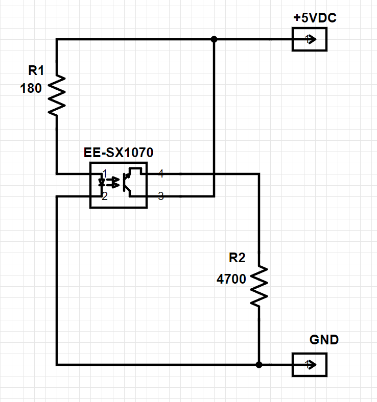
Below is the little board I put together. The resistor on the right is a 180 Ohm resistor to set the forward current through the emitter side of the opto to about 20mA. The other is a 4.7kOhm that is the Load Resistor for the transistor side. If you want to see how I landed on that value, I included details below in the Design Notes, but the gist is that I selected it to get the most out of my 0-5VDC range.

Or, to tie this in with an Arduino, instead of just reading the voltage on a multimeter:
Here I've just added in an Arduino Nano (I used one of these generic versions) to read the sensor voltage.
Calibration
Process
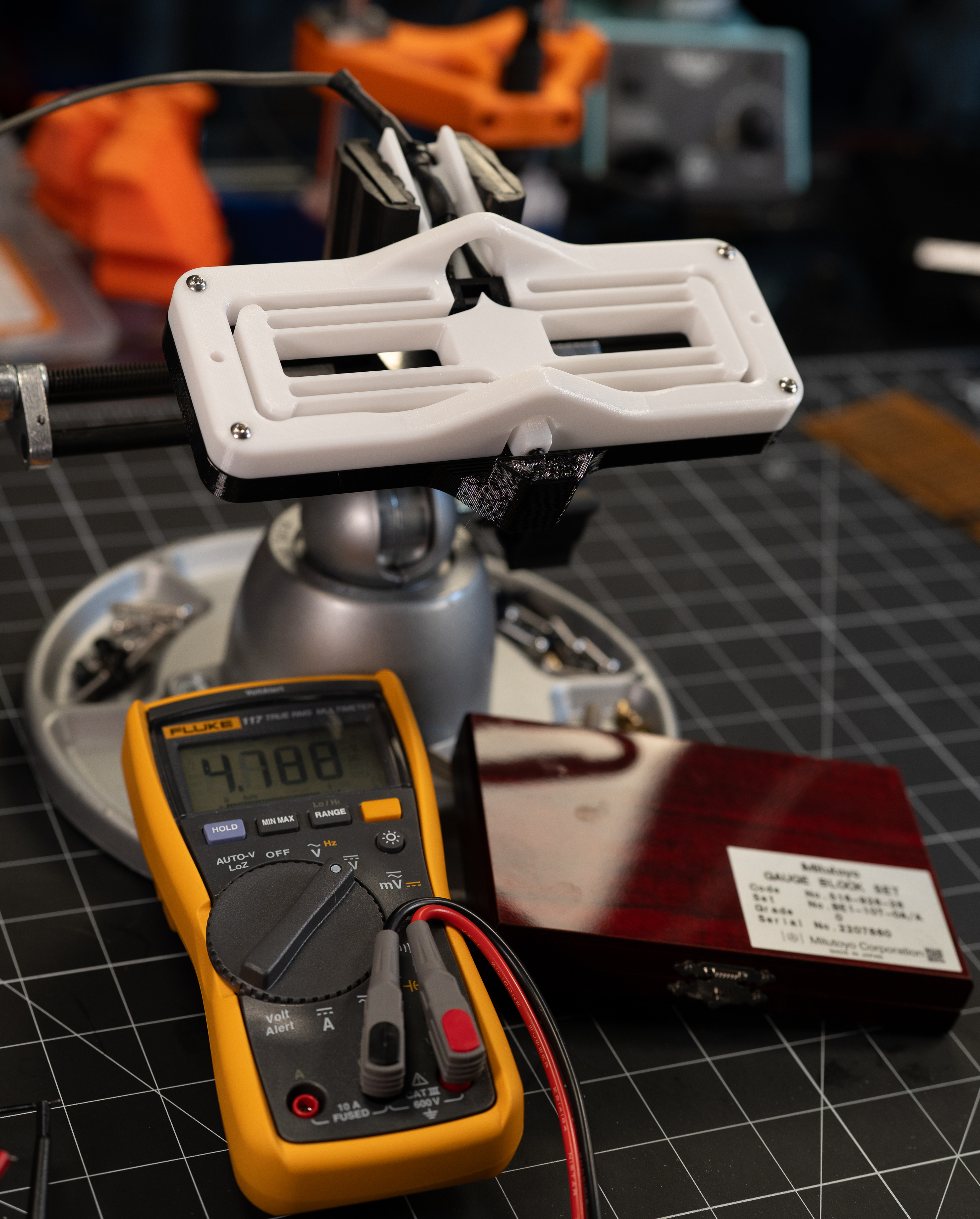
To calibrate the sensor, I fixtured it to the printed cal fixture and then held it in my trusty panavise. I just went with my handheld multi-meter to measure the output voltage as I stepped through each of the guage blocks in my little set of thin gauge blocks.

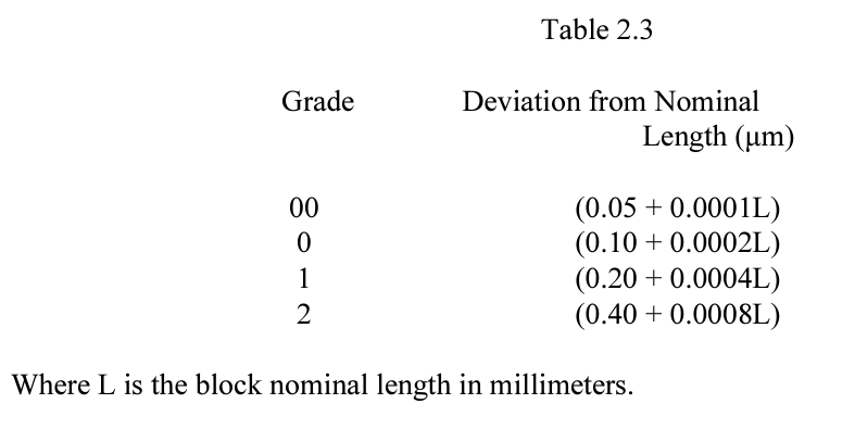
These blocks are ASME Grade 0. So they are certified accurate to 0.10um + 0.0002L. So for a 1mm block, this would be an uncertainty of 0.10um + 0.0002(1000um), or 0.3um. As a general rule of thumb, it's good to have your measurement tool 10x better than the thing you're measuring. So if our gauge blocks are good to the 0.1 um order of magnitude, then it should be a valid tool for calibrating a sensor down to the single digit micron(ish) range.
The above range came from the below table in this NIST handbook. Which is also just a great all-rounder on all things gauge block!
Since I recognize that not everyone loves expensive shiny blocks as much as I do, I also performed a couple of cals using feeler gauges in place of gauge blocks. You can really use anything, but just note that the uncertainty of your calibration is a direct function of the uncertainty of your calibrator(s).

Results
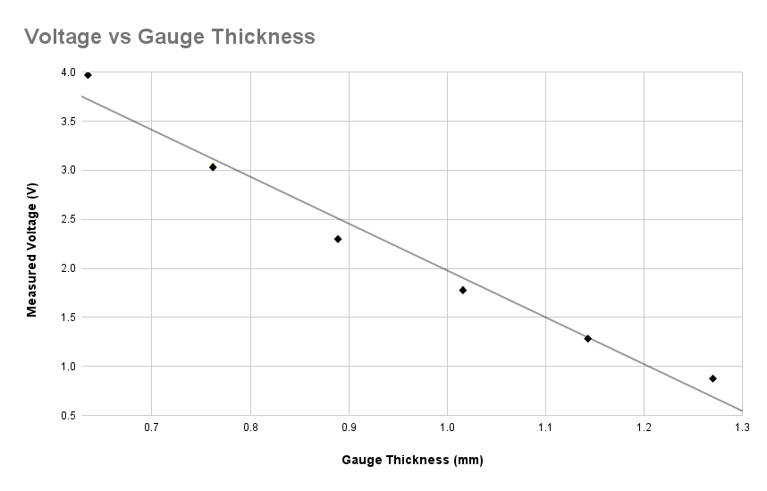
The slope of the trend line shown below is -4.78 V/mm. This is what would more commonly be referred to as just the "sensitivity" of the sensor. This gives the easiest option for converting voltage to displacement in use. Just divide the measured voltage by 4.78, and ya got yourself some millimeters (since the sign just says whether the sensor is getting more compressed, or less, the sign is sort of arbitrary).
I mentioned that this is the easiest option, which I suppose implies there is a more difficult one...kinda!
If the sensor is has a nonlinear, but repeatable response, then using a higher order fit or look up table may be worthwhile.
So how do we know if this is indeed the case? So glad I asked :)
We will need to look at the same data above, but just sliced and diced a slightly different way. First, we want to look at the difference between each point and the trend line. This deviation from the linear fit gives us the Linearity Error.
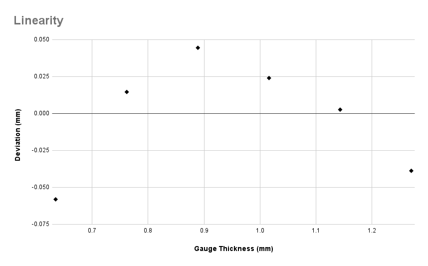
From the above, we can see that the sensor has a Linearity Error of about +/- 50um, which is about 2 thou for my freedom unit lovin friends. That's not great, but if we want to do any better than that, we'll need see how repeatably it follows this curve.
To do this, instead of looking at how far each measurement deviates from the trend line, we want to look at how much each measurement deviates from the average of measurements taken at that same location. The results are shown below. With everything other than the lowest measurement falling inside of +/-5um, it looks like we could get almost a full order of magnitude better performance by using a lookup table over a simple linear fit.

It should be noted that I'm glossing over quite a few assumptions and such here. For example, I haven't evaluated if the repeatability errors shown above are random errors. I don't know if any of the uncertainties may be time-variant. And I don't know how the calibration setup itself may have impacted the performance....Now don't get me wrong, if I were a company selling you this sensor, the marketing would undoutedly just have "5 MICRON REPEATABILITY" in bold, but I think it's helpful to keep in mind that your actual mileage may be lower :)
Design Notes
2024/01/20 - Initial design
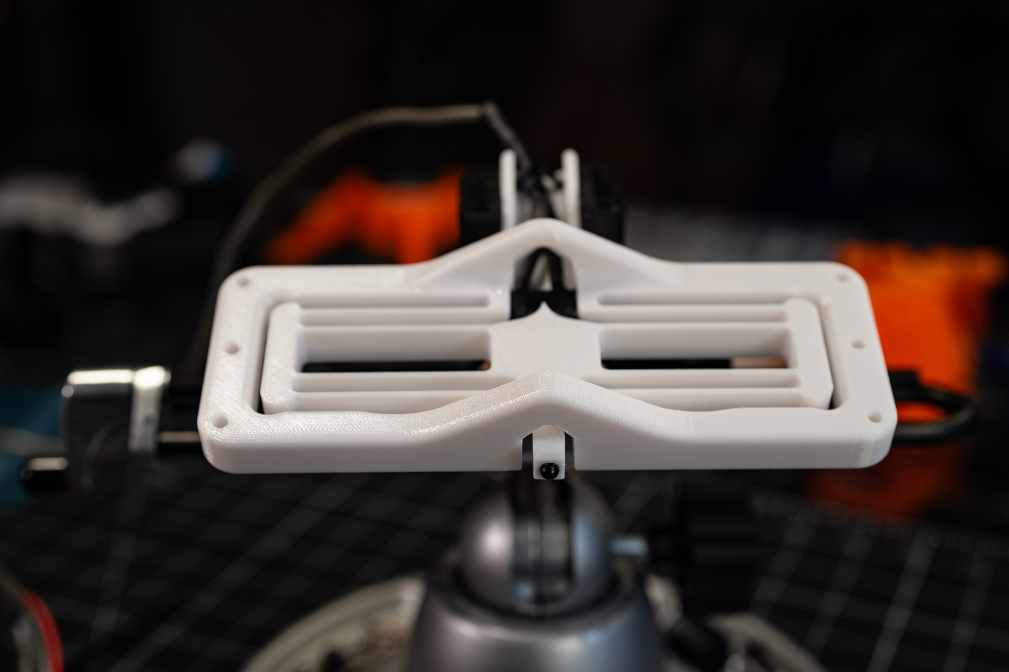
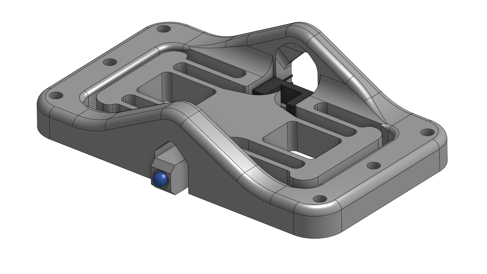
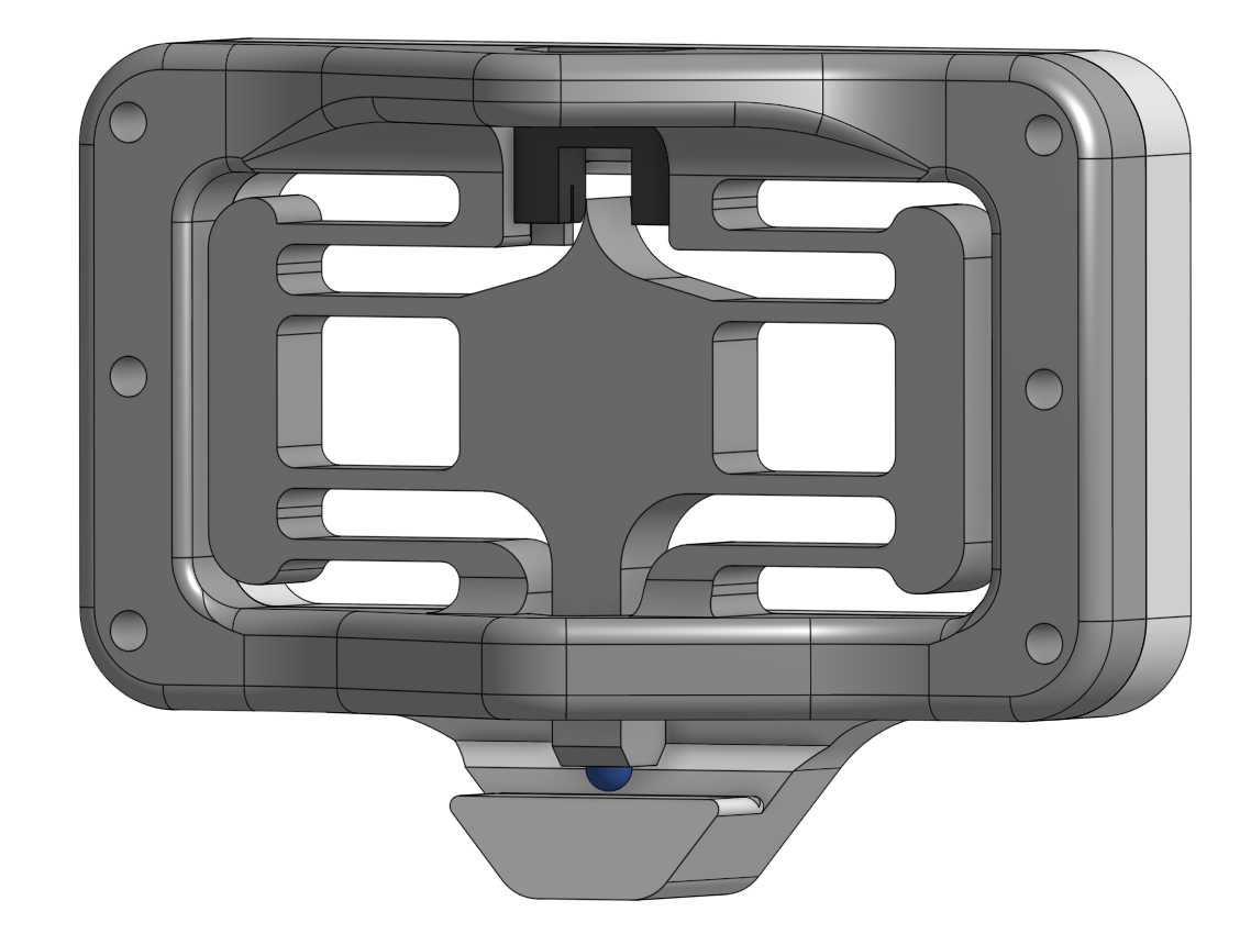
The base design concept is one that I have used/made many times over the years in various forms. It centers around a double compound flexure with one end of the moving platform extending out for the contact point, and the other side has a printed-in 'blade' for breaking the beam of the opto-interrupter.
To simplify the design a bit, I just settled for some out of plane assymetry to provide a clearing for the probe tip. I wanted something I could get on the machine quickly, but if I find myself having concerns that this is introducing parasitic motions it should certainly be possible to address this in a future rev.
I added an undercut on the wall next to the opto to avoid corner rounding or other print artifacts from causing the opto to not sit on the flat as intended.
For calibrating the sensor, I made a simple 'null frame' that I can use with some gauge blocks. The idea being to step through thicknesses of blocks and record the corresponding output voltage.
2024/01/22 - V2
Overall, V1 worked fine, but there are a couple of small tweaks I want to make.
The first is just to lengthen the leaf flexures from 20mm in V1 to 30mm in V2. The V1 was quite a bit more stiff than I want for most applications, so extending the leafs will reduce this stiffness. I probably should have also thinned them a little, since that gives more 'bang for the buck' on reducing this stiffness, but I opted to stick with the 2mm thick leafs for this one. Quick aside, but one...fun?...takeaway from V1, because of the high stiffness, it occurred to me that this same build can also be used as a load cell! Sooo, this is now a DualPurposeSensor project, I reckon...I wonder if that's already what the page is called by the time this is even seen by anyone but me...I wonder if this will ever be seen by anyone but me at all 😏
The second was to add an extension on the sensor end with tie points for cable ties. I found V1 very much in need of some strain relief for the cable coming off of the opto.
2024-01-24 - V2 Setup and Cal
For V1, I didn't bother fine-tuning the Load Resistor to maximize the range on the output voltage, but before calibrating V2 I wanted to take a closer look at this.
So I stepped through a range of resistor values and noted the null voltage for each. The below plot shows what I found. Note, this is on a 5VDC supply voltage. So the 3.3kOhm resistor got the null voltage up to a little over 3.7V. The voltage drop on the transistor should only be ~0.1VDC. So there should still be some more head room to increase this further, but I noticed that I was starting to lose range on the bottom end. So I'm going to stick with 3.3k for the time being.