 |
 |
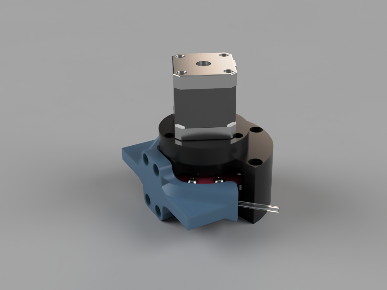
This iteration is the first thus far that I think counts as a "precision" pump! Separating the 'shoe' into a stand-alone component enables tuning the amount of compression to ensure a complete seal.
BOM
- Printed Parts
-
Rotor_Upper 
-
Rotor_Lower 
-
Frame_Upper 
-
Frame_Upper_Mirror (aka Frame Lower) 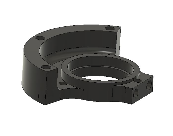
-
Shoe 
-
MotorMount 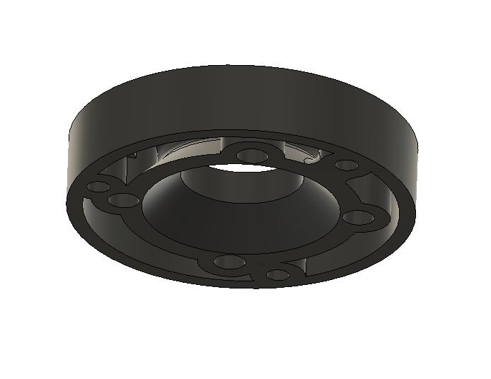
-
MotorCoupler 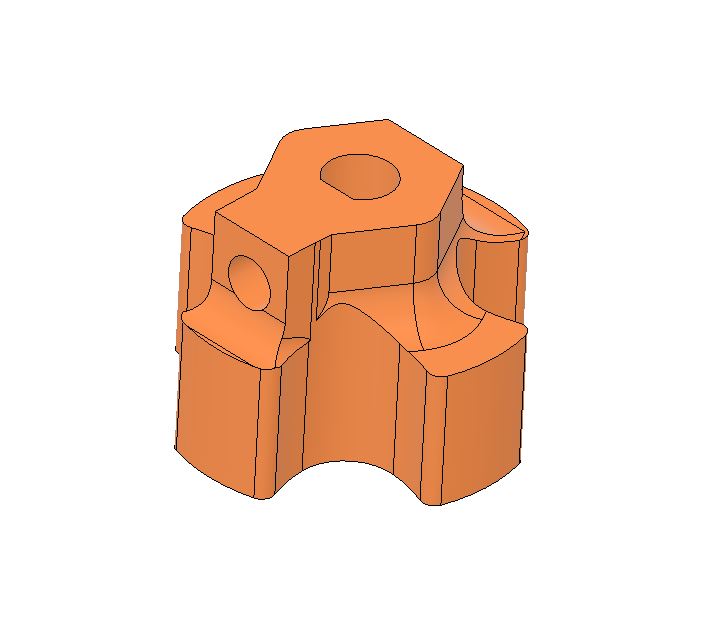
-
- COTS
- (Qty 7) M5x15 BHCS
- (Qty 20) M4 washers - OD needs to be equal to, or less than the OD of the inner race of the bearings.
- (Qty 13) M4x15 BHCS
- (Qty 4) M3x10 BHCS
- (Qty 1) M3x10 BHCS - if you have one available, an M3 set screw would be better. This is for the motor coupler.
- (Qty 7) M5x9.5 Heat Sets
- (Qty 13) M4x4.7 Heat Sets
- (Qty 1) M3x5 Heat Sets
- (Qty 10) 604-2Z - 4x12x4 bearings
- (Qty 2) 6806-2RS - 30x42x7 bearings
- (Qty 1) Nema17 Stepper motor
A bit more/more options on heatsets ifn you're interested
Build

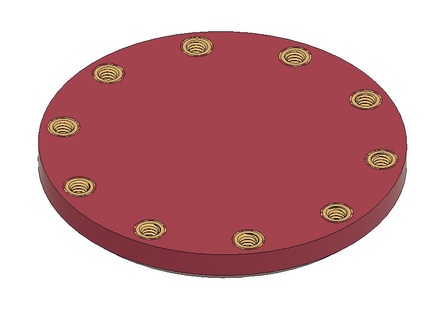
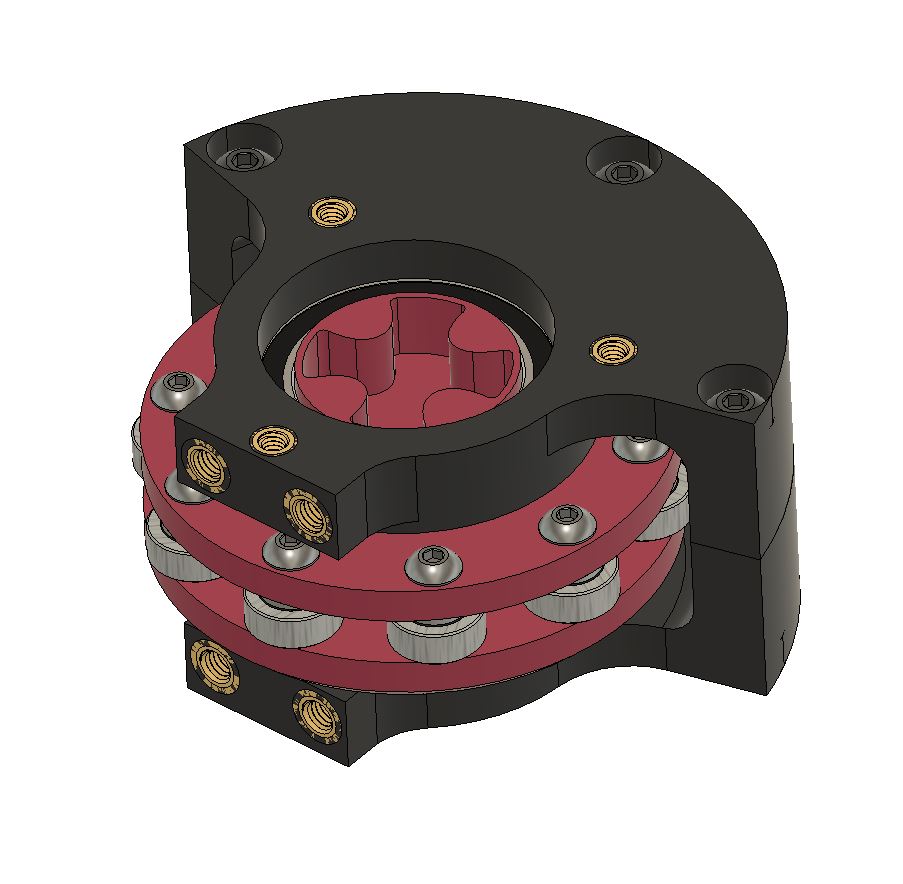
The above cross section shows the rotor config. The lower rotor gets 10 of the m4 heat sets, as shown in the below.
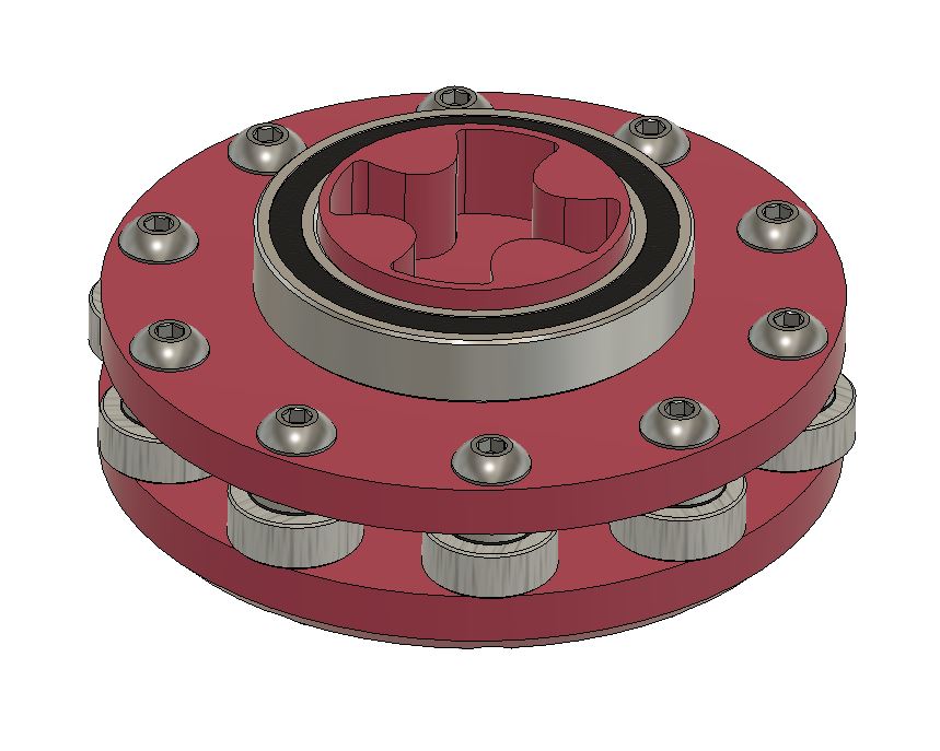
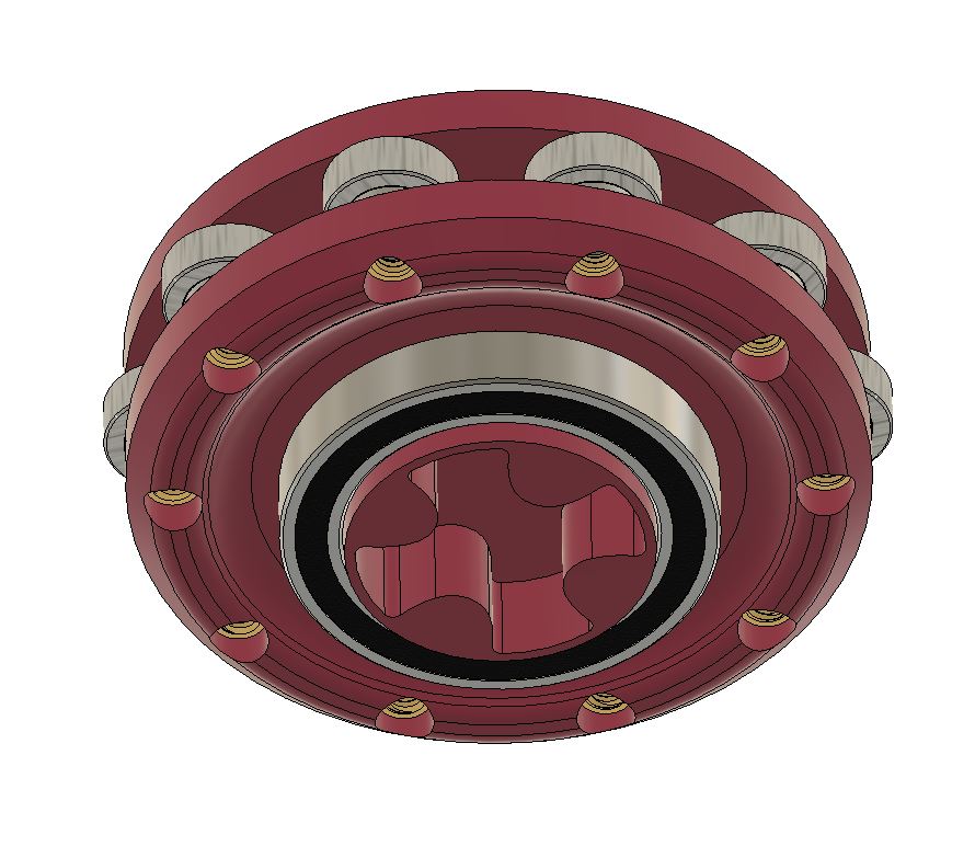
Sandwiched between the upper and lower rotors goes washer -> bearing -> washer on each m4x15 fastener. The large bearings then go on to both sides on the hubs. The sub assembly should look like the below.
 |
 |
You'll then want to get the m5 heat sets installed in the Frame_Lower. They are intended to be inserted from the bottom, but make sure to keep the through hole clear. The rotor assembly can then be inserted into the Frame_Lower. If the ID on your bearing mount came out too tight, you may want to install the bearing in the housing first. I would not recommend "pressing" the bearing in through the rotor assembly...although I guess it'd probably be fine...but why?

Next you'll want to get your Frame Upper prepped. It gets 3 of the m4 heat sets for the Motor Mount and 2 m5 heat sets for the shoe. It gets secured to the Frame Lower with 3 of the m5x15 fasteners.
Set this assembly aside, and get the stepper and Motor Mount. The stepper is fastened to the motor mount with 4 - m3x10 fasteners. The Motor Coupler, with its m3 heat set installed, is then attached to the servo by tightening the m3 against the D flat on the servo. The motor sub assembly should then look(ish) like the below.
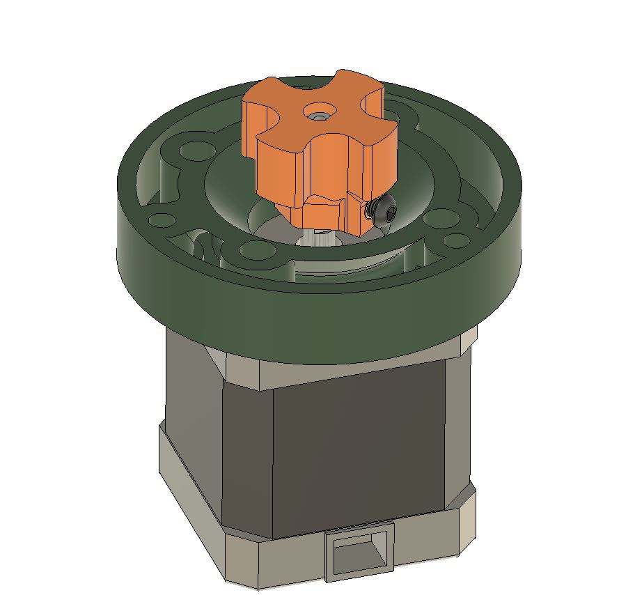
Do a quick test fit to make sure the coupler isn't bottoming out in the mated pocket on the top of the rotor. If it does, slide the coupler a bit further down the shaft. You want to make sure the motor mount is in intimate contact with the frame to not axially load the servo unnecessarily. If the coupler position seems good, good ahead and bolt 'er down.
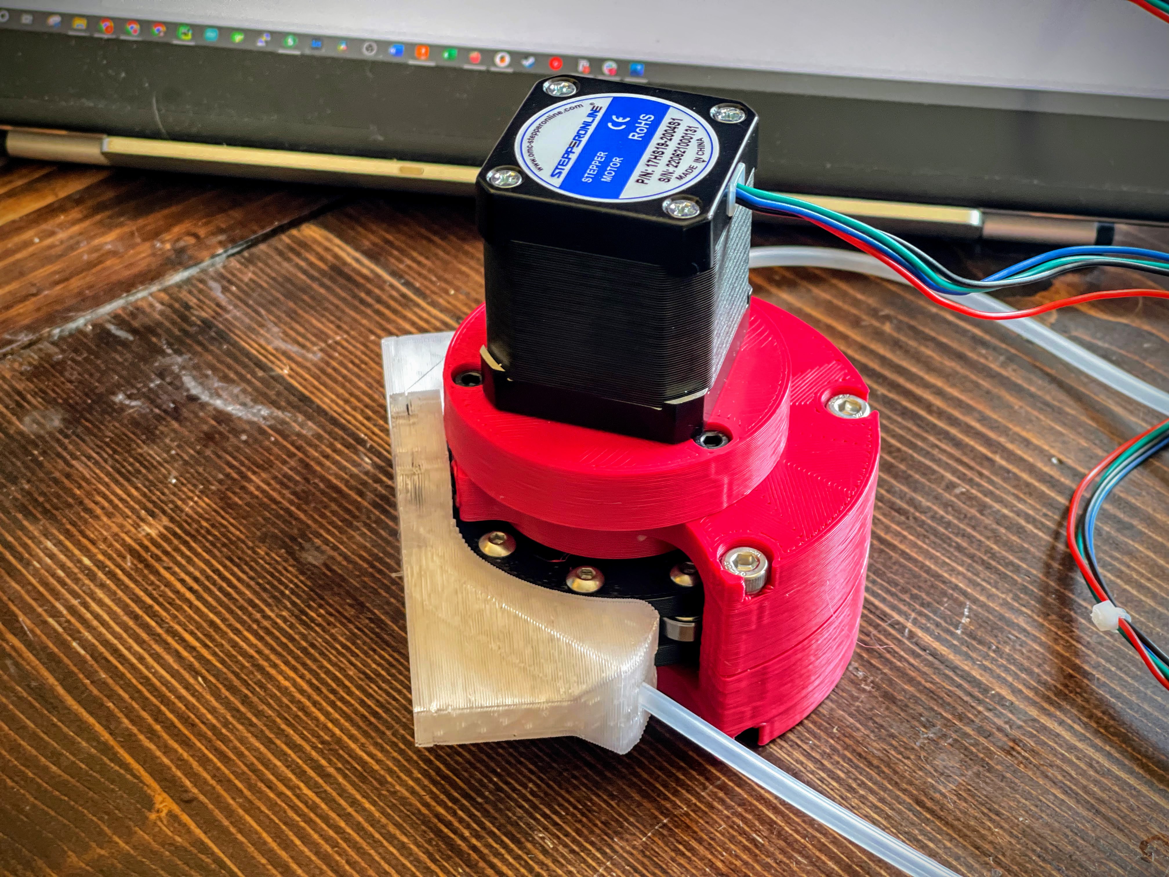
Then thread your tubing through the Shoe, going behind the two posts and try to generally nest it into recess. Then tighten the shoe to the frame until you reach the desired amount compression! I found an easy way to find the point of a good seal was to use a 30cc syringe with the tip in one of the tubing. Then tighten the bolts until what a bit of resistance starts, then tighten in a criss-cross pattern, each time pulling vacuum or applying pressure using the syringe. Once the syringe returns COMPLETELY to it's starting point, you're around the sweet spot. Maintain the pressure in the syringe for at least 10 seconds or so as a quick "leakdown" test. If it passes, you're good to go!
