This is one I've been thinking about building for quite some time, and I won't lie, I'm pretty excited to start breakin stuff!...er, I mean, quantifying the strength of my previous designs via destructive testing
Design
Objectives
The main objective here is a test cell for performing compressive and tensile testing. However, I don't just want to be able to measure standard test samples. I want to be able to test actual components and assemblies. Over the years I have ended up with quite a few 3d printed designs for structural components, like the various brackets I've made for assembling 2020 extrusion frames or my recent caster wheel build, and I would love to get some actual data on how much load these sorts of structures can withstand.
So to accomplish this, I will need something that can:
- Apply both tensile and compressive loads of up to 2.5kN (~500 lbf) - Admittedly, this was selected somewhat arbitrarily, but seemed achievable at a reasonable price and sufficient for the vast majority of my needs...at least for now
- Withstand offset loads - Because I will be testing 'real' parts, I can't assume that loads will always be along a single line of action. Unlike standard test samples, which can be designed/held such that loads are well-behaved and nominally symmetric.
- Data collection
- Load - I'd like to have a configuration that will support a somewhat modular load cell. This will allow for using load cells that are sized for the part under test, enabling a wide range of applied loads while still getting good signal-to-noise when needed (for example, when testing a small bracket, I may want to only use a load cell with a total range of 100s of Newtons, but if I'm trying to test something bigger, I may want a full scale range of 3kN).
- Displacement - At a minimum, I want to be able to measure the amount of strain being applied to the part under test. Ideally, I'm thinking I'd like to have at least three displacement measurements
- One measurement of the strain in the part. For this I'm thinking I'll consider the dsplacement between the load plates as this strain (the interfaces where the load will be passed into the part).
- Two measurements for the actuators (one for each). Ultimately I want to be able to run the linear actuators closed-loop from positional feedback.
- Temp - Cause always. I've been working in precision stuff for too long, what can I say
- Imaging - In addition to wanting to be able to get photos and video for my own enjoyment, I also would like to attempt to use an image-based system for some of the displacement measurements mentioned above.
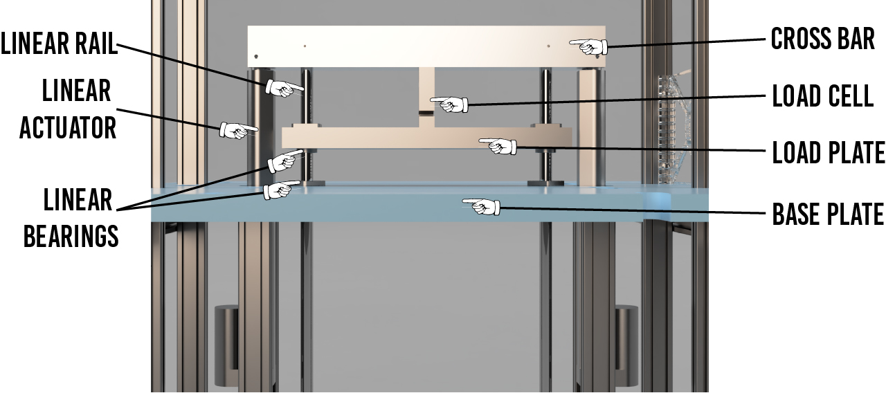
Design Overview
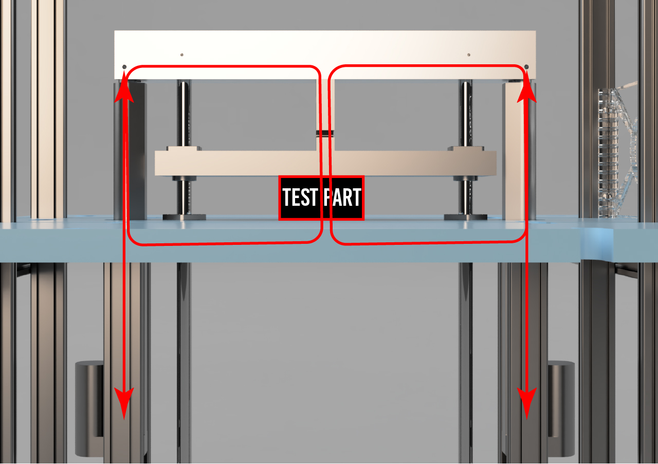
The basic design concept is pretty similar to most dual-column tensile testers that are common to most material test labs. With a symmetric set of linear actuators and linear guides on either side, used to drive a cross bar. The part under test is attached to both the cross bar and the base plate, and the actuators are driven to either pull on or squish the part.
The below image shows the load paths.
A heavy emphasis during the design was on making use of materials on hand wherever possible. Luckily, I had some large bits of aluminum scrap, as well as some 16mm linear rails and bearings left over from an old project. in case you're curious where some of the design decisions, like the use of a substantial chunk of alumininum plate for the 'Base Plate', for example, came from.
That's enough overviewin, on to the subsystems and components...don't act like you aren't excited.
Actuation
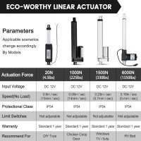
For the linear actuators for V1, I went with some low cost lead screw actuators with max capacities of 1kN each. I used these 12" (~300mm) travel actuators that I found for a little under $40 ea. I don't expect these to live all that long, since this sort of load profile is definitely not what they're designed for (especially the sudden load release when a part fails.), but I think they'll be perfect for initial development, code testing, etc. at the very least. Then I can upgrade these at the same time I make any other significant modifications I make for V2. This being my first load tester build, I'm fully expecting to find some additions/modifications wanted after a bit of use.
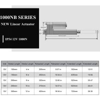
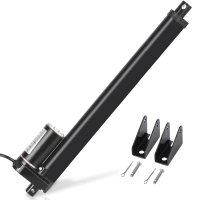
These actuators are intended to be pinned at each end with a 5mm pin, and are designed to only take a direct axial loading in either tension or compression.
Linear Guides
The linear guides serve two purposes in my design.
The primary job is to take up all lateral loads in the primary load path to ensure the linear actuators are not subjected to side loading.
The secondary, but similar (and still important) role is to also take up any lateral loads that would otherwise result in the load cell carrying a moment. That would produce measurement errors, so by constraining/guiding the load cell relative to the cross bar, the load cell's reading is insured to be along the prescribed axis.
I opted for these 16mm x 700mm steel rails that I purchased extras of for a project a while back. I mounted the rods rigidly into the cross bar (more detailed descriptions of the machined components below.) I paired these with two sets of LMK16UU linear bearings. One set mounted into the Load Plate, and the second set mounted in the Base Plate.
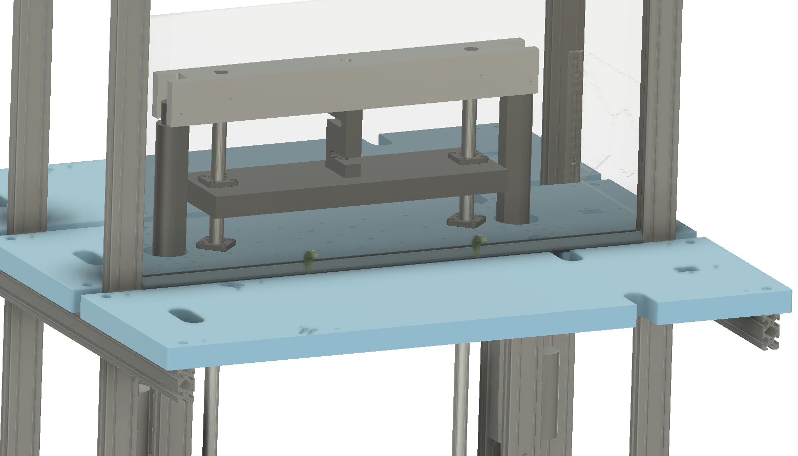
The below cross-section shows the bearing configuration a bit more clearly.
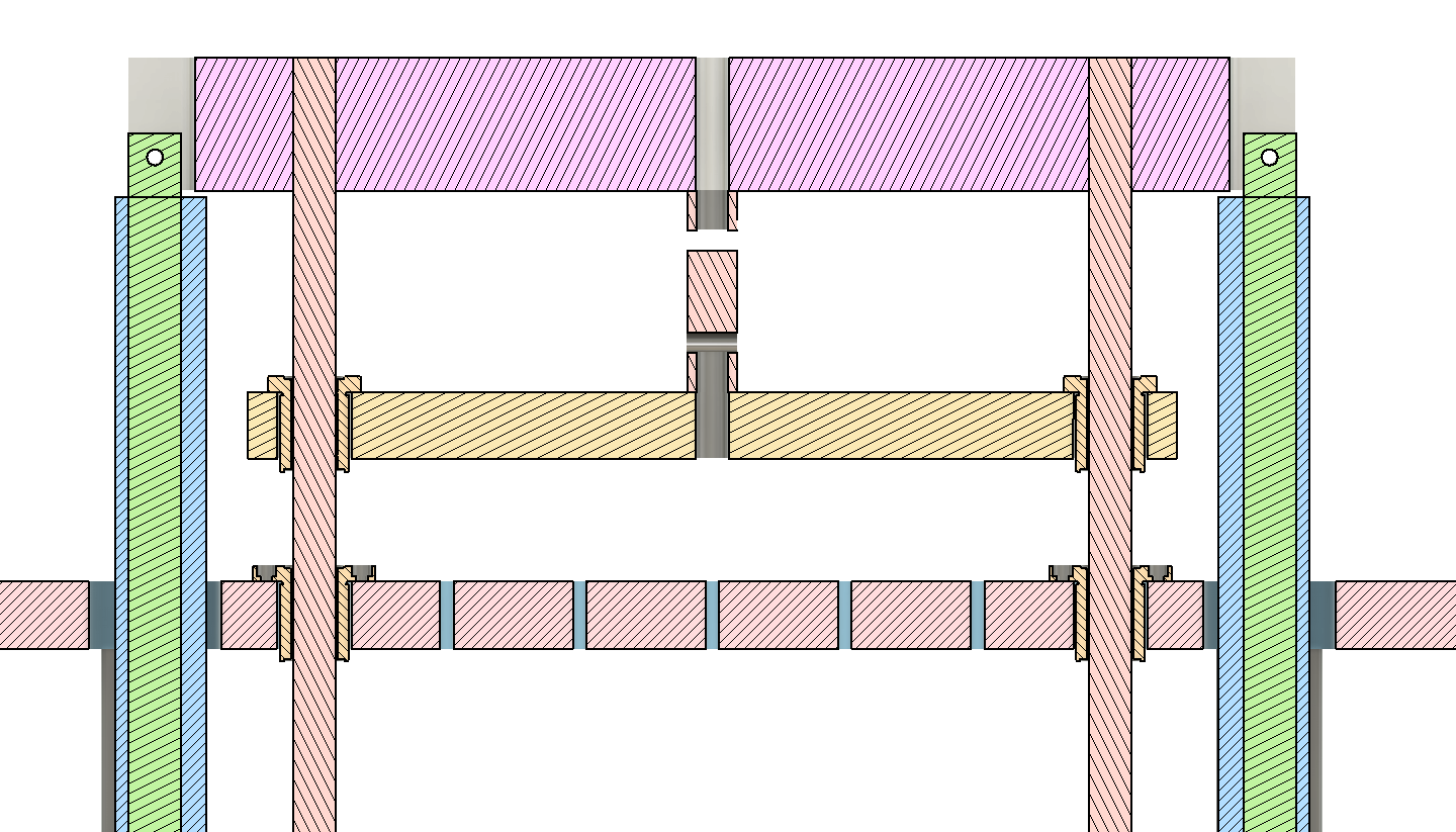
The fear with this sort of configuration is that the axes of these bearing holes need to be tightly toleranced to avoid binding. The benefit though, is that if right, they can be very stiff and don't require any fine tuning or adjusting.
So I decided to put some real faith in my little Precision Matthews mill, and go for it. However, to give myself the best shot possible, I wanted to make sure the spacing of the bearing holes was within the travel of the mill so that each set could be cut in a single setup.
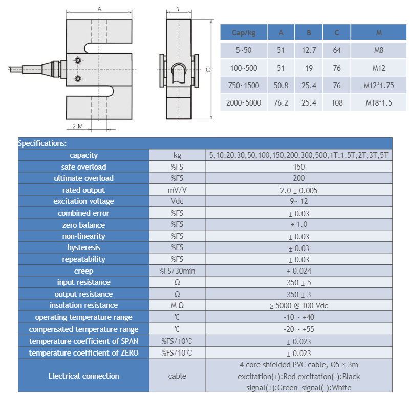
Load Cell
For now I'm using one of these 300kg load cells (it upsets me deeply that they class these things by mass...it needed to be said).
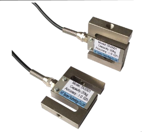
I had a lot of trouble trying to find a datasheet for the "PSD-S1" model number marked on the load cell itself. But I found this TAS501 datasheet that appears to match up in all of the metrics I have available (and looks identical). So my assumption, until proven otherwise, is that this is just a relabeling of the same generic load cell.