Assorted (hopefully) "Useful Stuff" Projects
Like the bucket of assorted fasteners on that bottom shelf, this category is for stuff that I didn't know how to group...oh, and speaking of those fasteners, check out the little sortin fella!
2020 Aluminum Extrusion Hardware
|
Quick Bolt Sorter
|
General Purpose Turntable - Gen1
- Details
- Parent Category: BubsBuilds Projects
- Category: Assorted (hopefully) "Useful Stuff" Projects
 |
Every project I work on that includes fasteners seems to end up accumulating a pile of unsorted, random bolts and their buddies. Usually these piles just find their way into what will be their indefinite home...the bolt bucket. So I've long thought it would be amazing to have a contraption to handle this for me, and over the years have tried a few, shall we say, 'not so fruitful' attempts to rig something up. The last couple of months I've been playing around with trying to build something 'sieve-like' for sorting bolts by their heads. If you aren't familiar with sieves, here's an article from some random website that came up in the first few Google results ¯\_(ツ)_/¯
 |
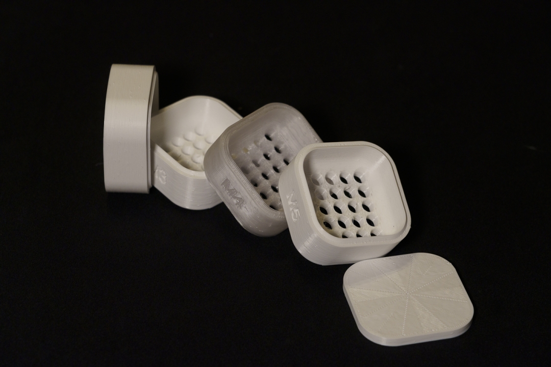 |
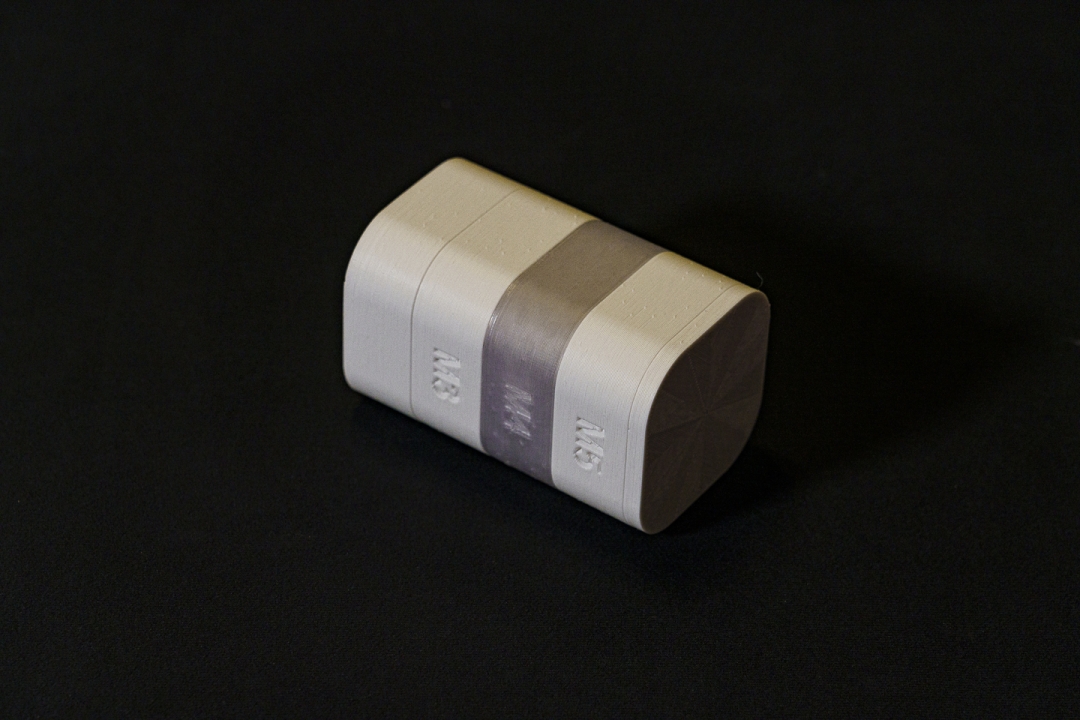
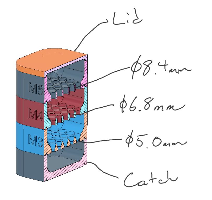
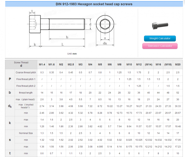
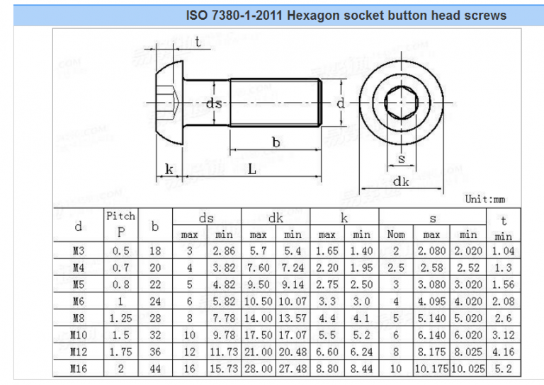
There's nothing too special in how it works, each layer has an array of holes. The holes of that layer are just smaller than the diameter of the head of the fastener that you want to 'capture' in that layer. The below cross-section shows the hole sizes for this 'first gen' set of screens. I selected these values based on the BHCS and SHCS head sizes ('dk' value) on the tables here.
Obviously this doesn't solve all of my sorting woes, but as you can see from the little video (is there anything worse than having to listen to your own voice?? :) ) it works pretty damn well for at least tackling this specific piece of the problem!
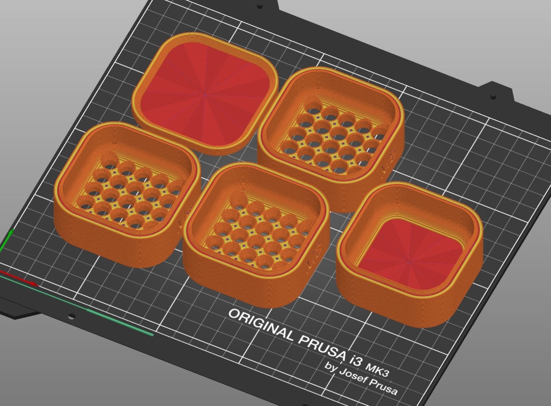
I printed mine from White and Clear Overture PETG, with all five parts printing on a single build plate in a little under 7 hours.
I plan to add additional screens over time, and, while I really like this little dude and have already tossed one in each of my toolboxes, I still have hopes for something that can handle the full range of crap that bolt bucket has to offer! If you have ideas for how to make that dream happen, want to suggest screen sizes that you think would be must-haves, or just want to follow along to see how it evolves, you can follow me on Printables.
Screens
BHCS & SHCS - Metric

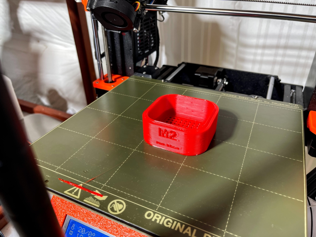
M2 - 3.6mm pores
M2.5 - 4.3mm pores
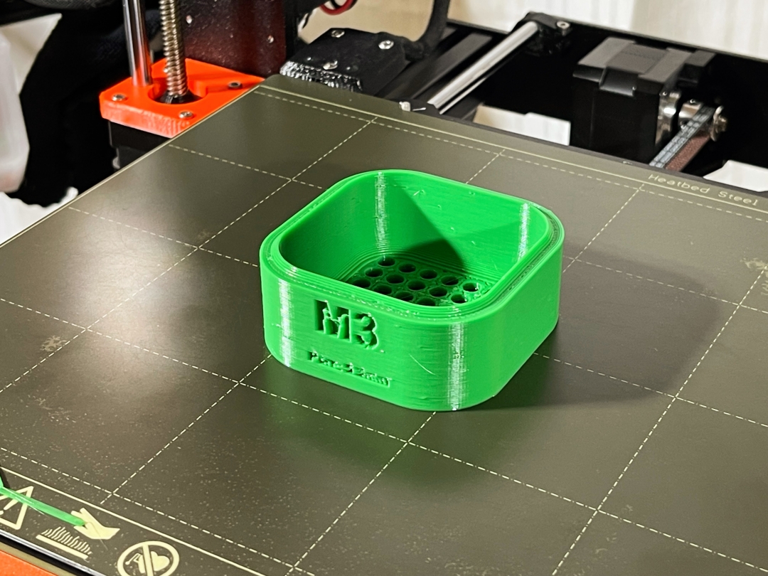
M3 - 5.3mm pores
M6 - 9.7mm pores

I printed the one shown in Green Overture PETG with a 0.6mm E3D Revo nozzle.
Spacers
The spacers are intended to add some extra volume to a given 'chamber' of the sieve to allow for longer fasteners, or slightly more fasteners (ultimately going to be limited by the number of 'pores' per screen, of course.)
"Unit Cell" Spacer - 27mm
This spacer is the same height as the other (current) screens at 27mm from flat to flat.
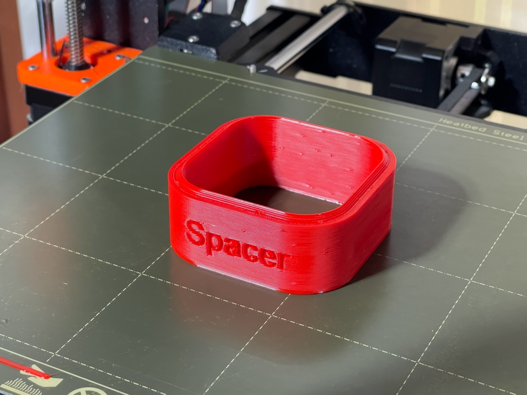
I printed the one shown in Red Overture PETG with a 0.6mm E3D Revo nozzle.
Other
No6 - "Bugle" Head...? New to me, but that's what the box says ¯\_(ツ)_/¯
I think this should work for most #6 wood screw heads, but I sized it specifically based on some wood screws I have around that I wanted to sort out.
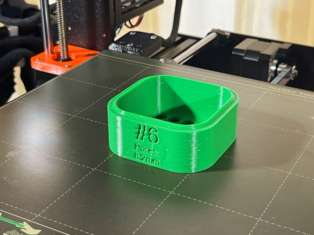
I printed the one shown in Green Overture PETG with a 0.6mm E3D Revo nozzle.
- Details
- Parent Category: BubsBuilds Projects
- Category: Assorted (hopefully) "Useful Stuff" Projects
A (relatively) simple general purpose rotary turntable. Intended for any of those, "Hmm, I'd really like to spin this around" type of projects, with the various mounting interfaces on the top surface aimed at providing flexible mount options to interface to these various tasks.
 |
 |
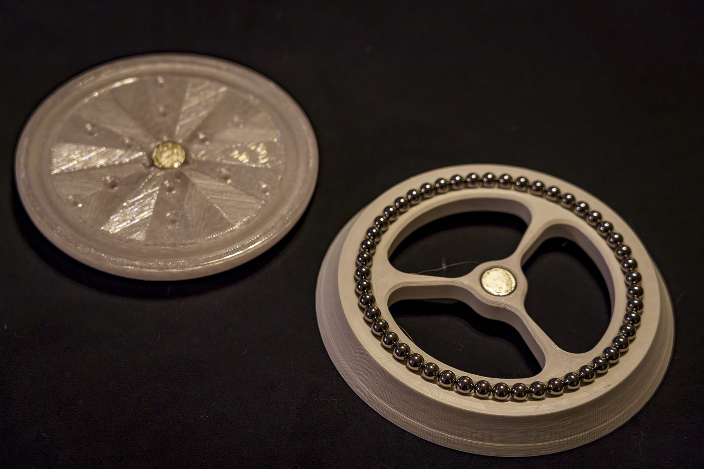
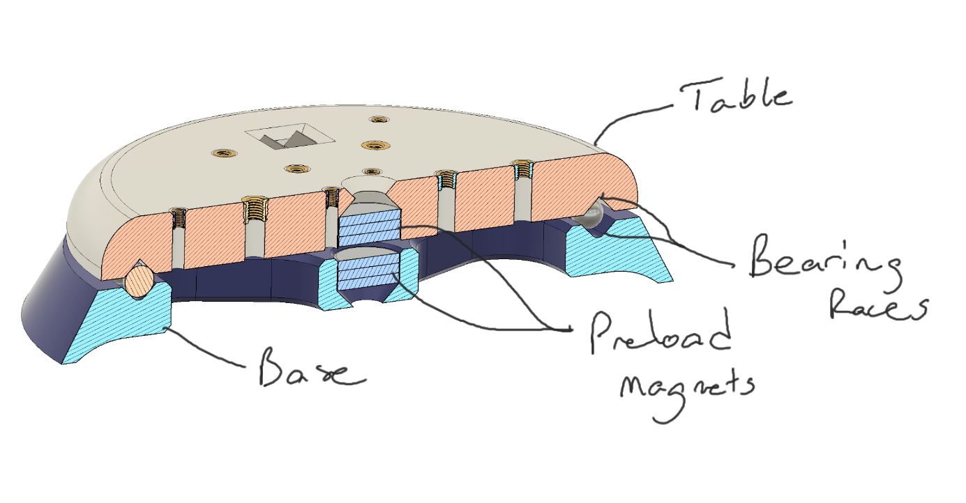
There are V-grooves on both the Base and the Table to serve as the bearing races, and these are filled with 3/8" steel balls (or, if you play with balls as much as I do, you may want this bad boy, which I recently discovered with great glee). The grooves are sized to fit 34 balls in total, but you can use less if you'd like. However, it will be a little more noisier and less smooth, but not like you're looking for air bearing performance from your 3d printed rotary table...I hope :) The bearing is preloaded (and parts held together) with sets of 20x3 disk magnets (3 on each side).
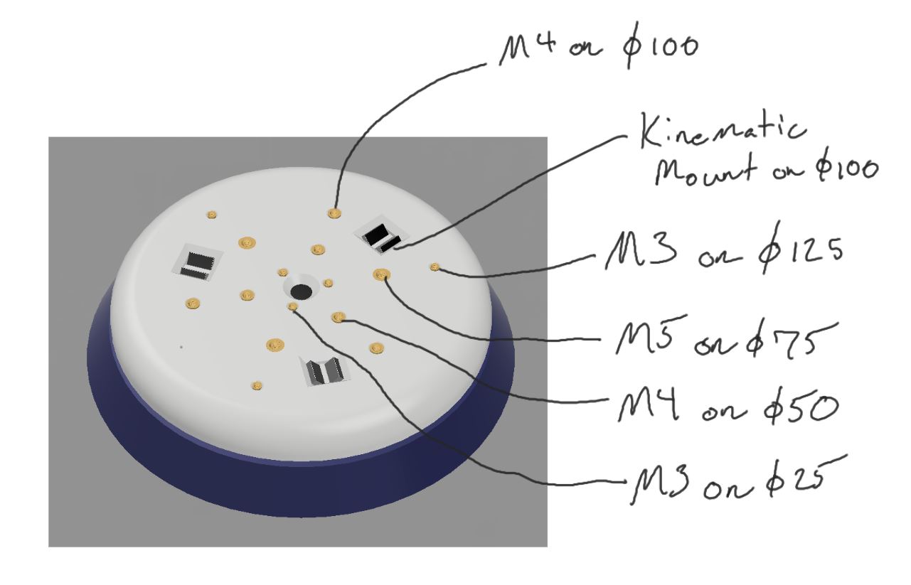
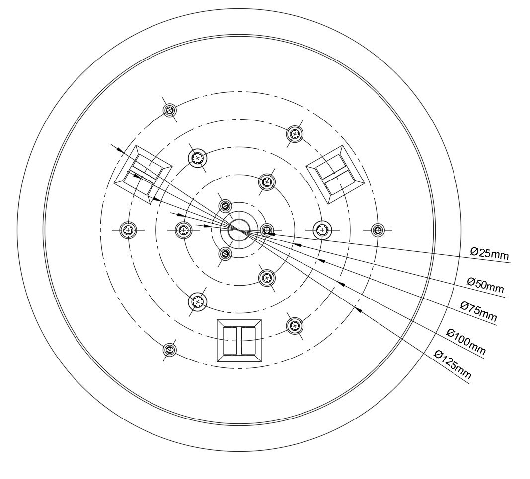
The table has locations for a variety of mounting options, as shown in the below. These interfaces are:
- 3x M3x5.7 Heat set inserts on a 25mm circle
- 3x M4x8.1 Heat set inserts on a 50mm circle
- 3x M5x9.5 Heat set inserts on a 75mm circle
- 3x M4x8.1 Heat set inserts on a 100mm circle
- A 'Maxwell clamp'-style kinematic mount on a 100mm circle, sized for between 3/8"-1/2" (9.5-12.5mm) diameter balls. The contact points and preloads are provided by 6 of these 12x6x3 bar magnets.
- 3xM3x5.7 Heat set inserts on a 125mm circle
 |
 |
 |
 |
Assembly Tips
First and foremost, KEEP TRACK OF YOUR MAGNET POLES! Few things more frustrating that waiting for the parts to print, the glue to dry, your fingers to separate...and then floating mount.... Don't do it, definitely a check thrice, glue once situation.
Once everything has had plenty of time to cure and dry, I clean the surfaces of the kinematic mount magnets to ensure there's no left over CA muckin up ma mount. I just take some of those long q-tips, sorry, "Cotton Swabs", and some acetone and dip, wipe, repeat until there's no residue left and I've got nothing but nice, shiny neodymium.
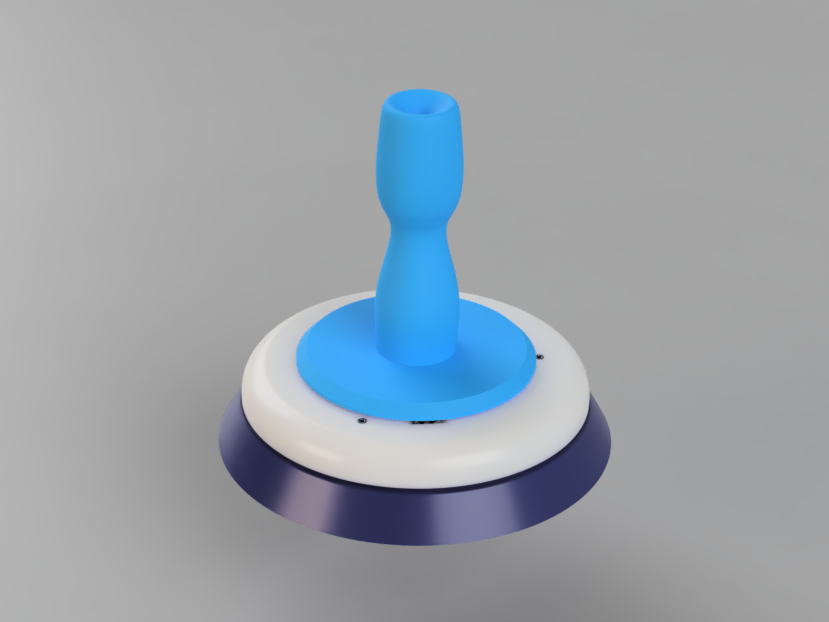
Paper Towel Adapter
 |
 |
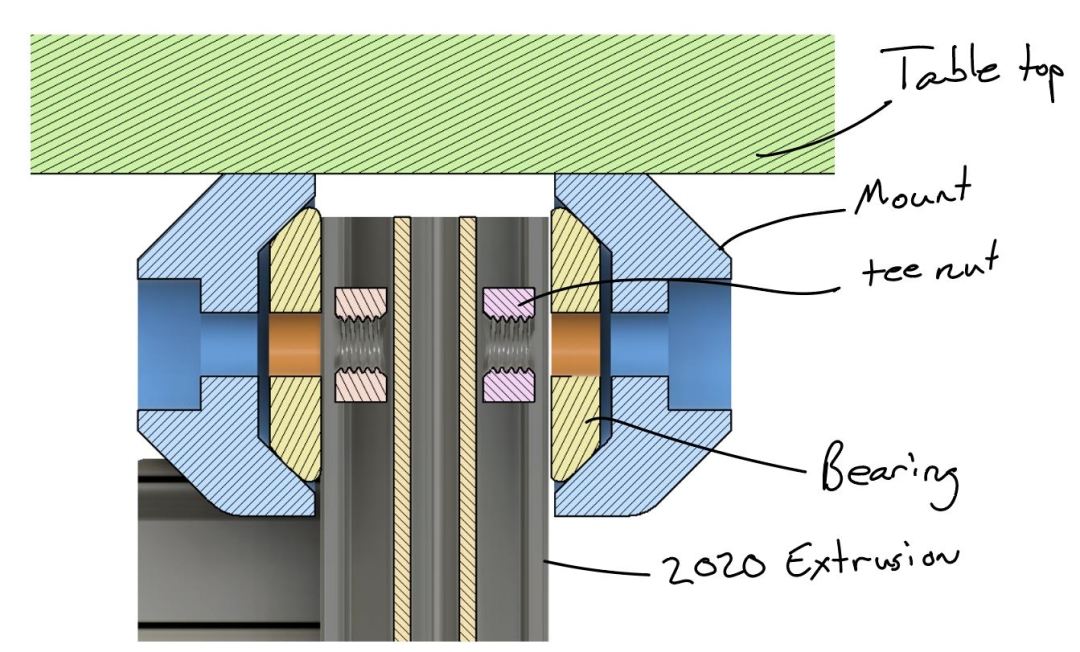
If you really want to flex your love of determinism, have I got the paper towel holder for you! This paper towel holder adapter uses the kinematic mount points of the turntable. Finally, a paper towel holder with a central axis that's stable despite CTE differences...amma right???
Curious about the...interesting...shape of the towel holder itself? There is actually a reasoning behind the bizarre choice of contour. There are two functional (or allegedly functional) drivers for this geometry. The first is that I wanted to try to define the contact regions with the paper towel tube, so the concave regions top and bottom result in two lines of contact with the paper towel roll at those two heights....for those precision engineering nit-pickers, yep, it's overconstrained....paper towels ¯\_(ツ)_/¯ The second reason is to introduce some compliance to account for variations in paper towel roll sizes (at least within a range), since a full roll has quite a bit of hoop stiffness (resistance to growing in diameter...ish). So as you can see in the cross section below, the contact regions have a variable thickness.
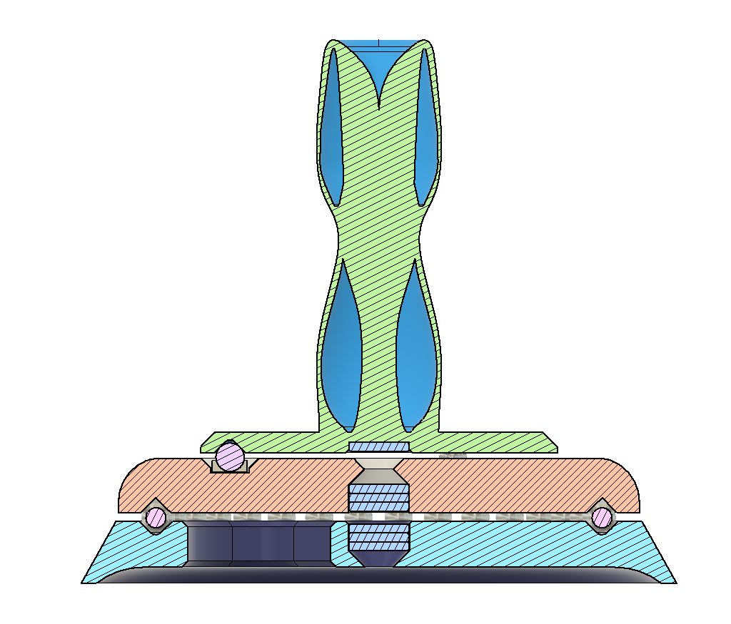
The original plan, and the first version I made, was for this to be a TPU component, but I've since printed it in PETG and it works just dandy. The TPU version does have a much better 'feel', in my opinion, but I'll gladly take the printing speed of PETG over the slight increase in enjoyment when swapping paper towel rolls. But if you want to really showcase the 'compliant mechanism' aspect, TPU is definitely the way to go.
- Details
- Parent Category: BubsBuilds Projects
- Category: Assorted (hopefully) "Useful Stuff" Projects
Assorted connectors, brackets, and such I've made for designs using 20mm x 20mm t-slot aluminum extrusion.
Hinges/Pivots
Design gist
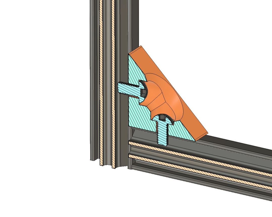
All of these pivots have the same basic design for the pivot mechanism. The annotated (at least technically, if you can read my hieroglyphs) cross section below shows the basics.
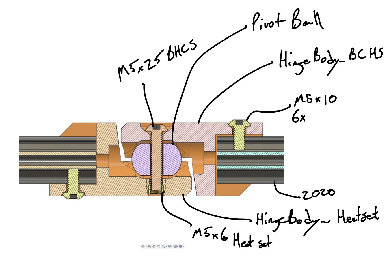
There are three main parts to the assembly, the Pivot Ball and then two Hinge Bodies. By relying on the ball pivot within the load path, the pivot can operate more smoothly even with misalignment in the 'bearing'. Although the ball pivot does smooth the movement, I wouldn't really recommend these for any sort of regular-use hinge application. While a shoulder bolt could be swapped in place of the M5x25 to make this into a more proper hinge, it would require sliding friction between printed components. Should be fine for a hinge that is only going to see occasional use.
The main differences between the below are in the Hinge Bodies, with each having different attachments to the extrusion to enable different configurations.
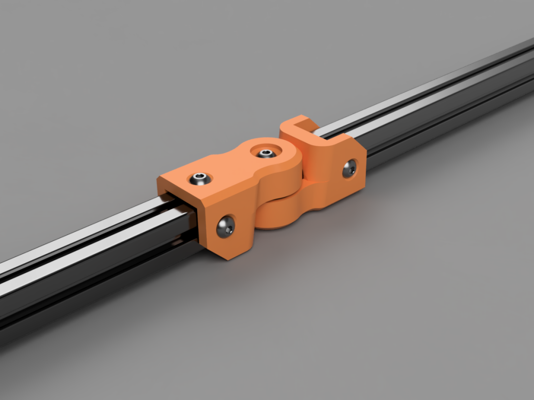
In-line - Single
 |
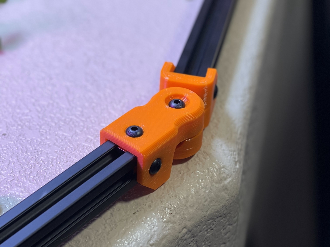 |
This is an in-line pivot and is the simplest and most compact of these hinges (at least as of when I'm writing this). It has three fastening points on each hinge body, but all of them are in the 'end' location. So this would not be an idea choice for anything that's going to be cantilevered with any appreciable load on it. Works great for a static frame that needs to have some odd angles in it. If you don't want to use heat sets (but if not, you're really missing out :) ) you can also just print two of the 'BHCS' bodies, and use an M5x30 with a nut.
In the pictured build:
- Hinge bodies and PivotBall - Printed with 0.48 layers on 0.6 nozzle in Orange Overture PETG and Black Overture PETG
- Heat set insert - M5x6 - I've been using these, but any similar option should work.
- Fasteners - I pulled mine from this kit that I've rebought a few times now.
- M5x10 (Qty 6) - These are for the attachments to the 2020
- M5x25 (Qty 1) - For through the pivot
- 2020 Extrusion - I've bought many brands and most are all pretty much the same. I've rebought this brand several times and been happy with the price/ft compared to the others, but I know that also can change any given day....yea Amazon :)
- T-nuts - I don't buy anything other than this style of T-Nut anymore. Can be dropped in, they stay put, they are available in different fastener size options....I just love them...¯\_(ツ)_/¯ hey, we've all got our thing
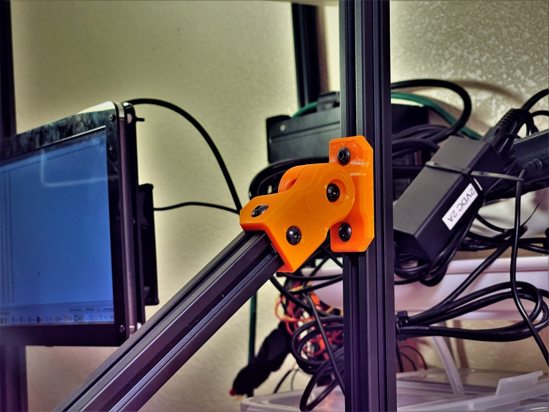
90 Degree
 |
 |
This one is for a hinge/pivot where the extrusion being pivoted is 'normal' to the one it is being attached to...didn't make sense? Look at the picture and you figure it out! :)
The parts and materials are all the same as the ones listed about, with the exception that the printable files can be found here on Printables.
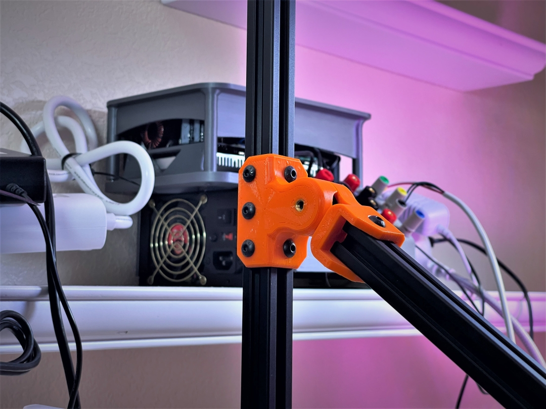
Midspan
 |
 |
A pivot/hinge for 2020 aluminum extrusion. The hinge is made up of three printed parts, none of which should need any supports, brims, etc. I designed it for introducing odd angles into 2020 extrusion frames. I've now made a few different variants on this pivot, this one is intended for when one frame member needs to come in at an angle, midspan of another member.
I printed mine from PETG on a 0.6mm nozzle and it takes about 2 hours for the set.
Hardware:
- HingeBody_Midspan.stl, HingeBody_BHCS.stl, and PivotBall.stl - Parts to print. I printed mine in both Orange and Black Overture PETG.
- m5x6 Heat Set insert - I used one of the 6mm lengths from this kit, but anything under 7mm length should be fine.
- m5x10 BHCS and m5 t nuts
Folding Table Hinge
Printables | Thingiverse
Details on the folding table hinge can be found here
 |
 |
90 Deg Elbow
 |
 |
Just a little 90 degree elbow. Configured for at least two M5x10 fasteners per extrusion (can be three on the long side if you also add the one in the corner, as shown in the images.)
Each prints in under a half an hour (with my settings) and shouldn't need any brims, supports, etc.
Hardware pictured:
- Corner_90.stl - I printed mine from Blue Overture PETG. Full print settings in the 3mf file available on Printables et al.
- M5x10 BHCS - The 'meat' of the plastic at the bolt interfaces is 5mm thick and the holes are nominally 5.5mm diameter...deviate as you wish :)
- M5 t-nuts - I love the little spring-loaded t-nuts that are drop in (don't have to be slid in from the end) and preloaded to stay in place.
Tees
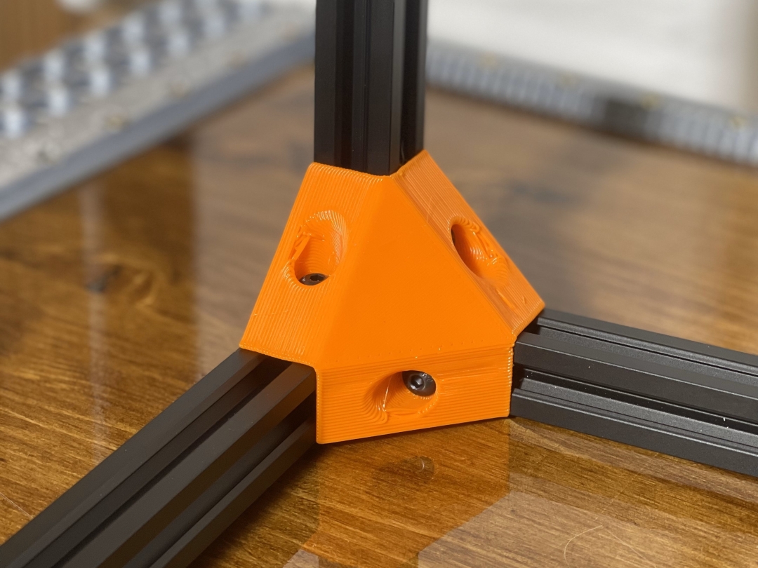
3-way Tee
 |
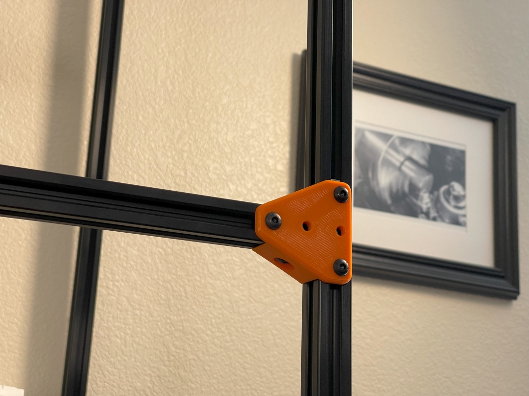 |
A 3-way tee for 2020 aluminum t-slot extrusions. Provides a sturdy, square corner for frames and the like.
Each one takes about 30 min with my slice settings (0.48 layers on a 0.6 nozzle, full settings in 3mf file on Printables)
Pictured hardware
- Tee_3-way.stl - Pictured one was printed in Orange Overture PETG.
- M5x10 BHCS - Should work fine with any M5x10, but I sized it with BHCS in mind.
- 2020 Extrusion - I've bought many brands and most are all pretty much the same. I've rebought this brand several times and been happy with the price/ft compared to the others, but I know that also can change any given day....yea Amazon :)
- T-nuts - I don't buy anything other than this style of T-Nut anymore. Can be dropped in, they stay put, they are available in different fastener size options....I just love them...¯\_(ツ)_/¯ hey, we've all got our thing
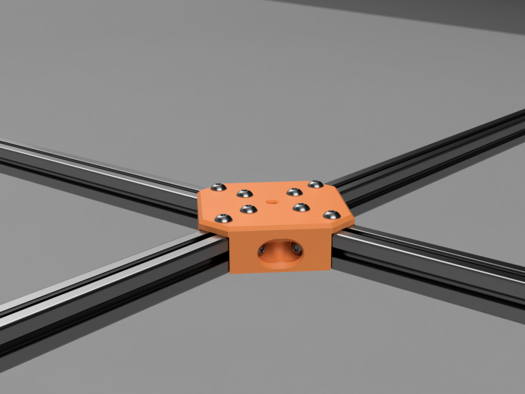
4-way Tee
 |
 |
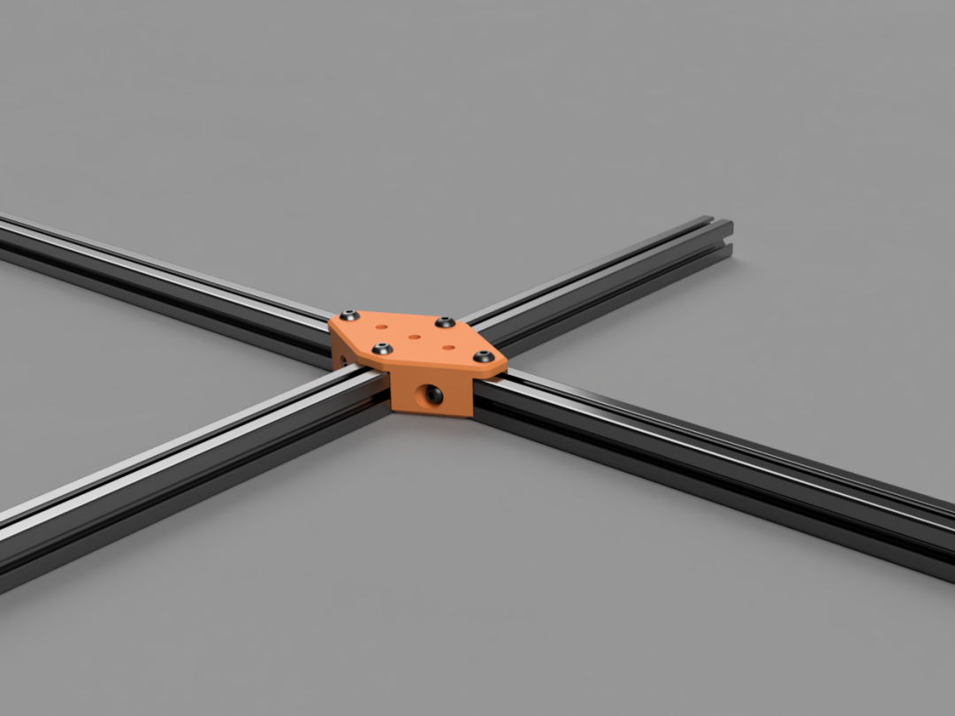
A 4-way tee for 2020 aluminum t-slot extrusions. Provides a sturdy, square corner for frames and the like.
Each one takes about an hour with my slice settings (0.48 layers on a 0.6 nozzle, full settings in 3mf file on Printables)
Pictured hardware
- Tee_3-way.stl - Pictured one was printed in Orange Overture PETG.
- M5x10 BHCS - Should work fine with any M5x10, but I sized it with BHCS in mind.
- 2020 Extrusion - I've bought many brands and most are all pretty much the same. I've rebought this brand several times and been happy with the price/ft compared to the others, but I know that also can change any given day....yea Amazon :)
- T-nuts - I don't buy anything other than this style of T-Nut anymore. Can be dropped in, they stay put, they are available in different fastener size options....I just love them...¯\_(ツ)_/¯ hey, we've all got our thing
4-way Tee - Full
A 4-way tee for 2020 aluminum t-slot extrusions. Provides sturdy corner for bringing 4 extrusions to a square corner.
Each one takes about an hour and a half with my slice settings (0.48 layers on a 0.6 nozzle, full settings in the attached 3mf file.)
Corners
Square Corner
 |
 |
Designed to fasten 2020 Aluminum Extrusions to make cubes with flush edges. Not intended to be particularly high load capacity, but I've built quite a few frames from this general design, and they are working just fine for my needs! Holes are designed for M5x16 BHCS fasteners, but slightly shorter (maybe down to 12mm...maybe...?) should work.
Mine have printed fine without supports, brims, etc.
I printed these in Orange Overture PETG with 0.48 layers on a 0.6mm Revo nozzle.
Other Stuff
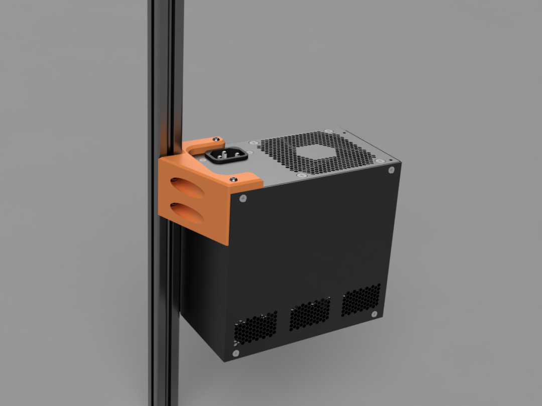
PSU to 2020 Mount
 |
 |
A bracket for attaching an ATX (regular ol' computer power supply) to 2020 extrusion, but please note, although I show it suspended in a vertical orientation with just this bracket, I wouldn't recommend it! This was designed, and is currently used, with an additional support below the supply. This bracket will support the weight of the supply by itself, but my concern is whether that would stay stable long term, after exposure to heat from the PSU.
Should print fine without supports, brims, etc.
I printed the one shown with 0.48mm layers out of Black Overture PETG.
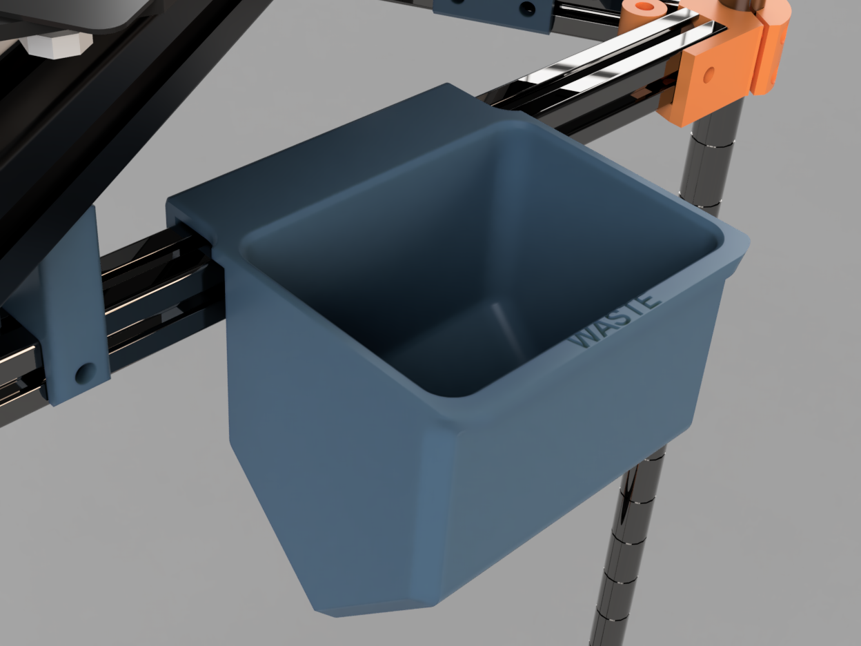
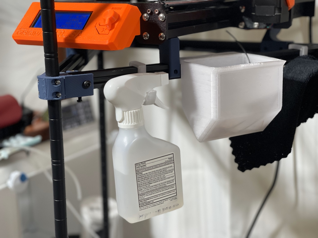
Waste Bin
 |
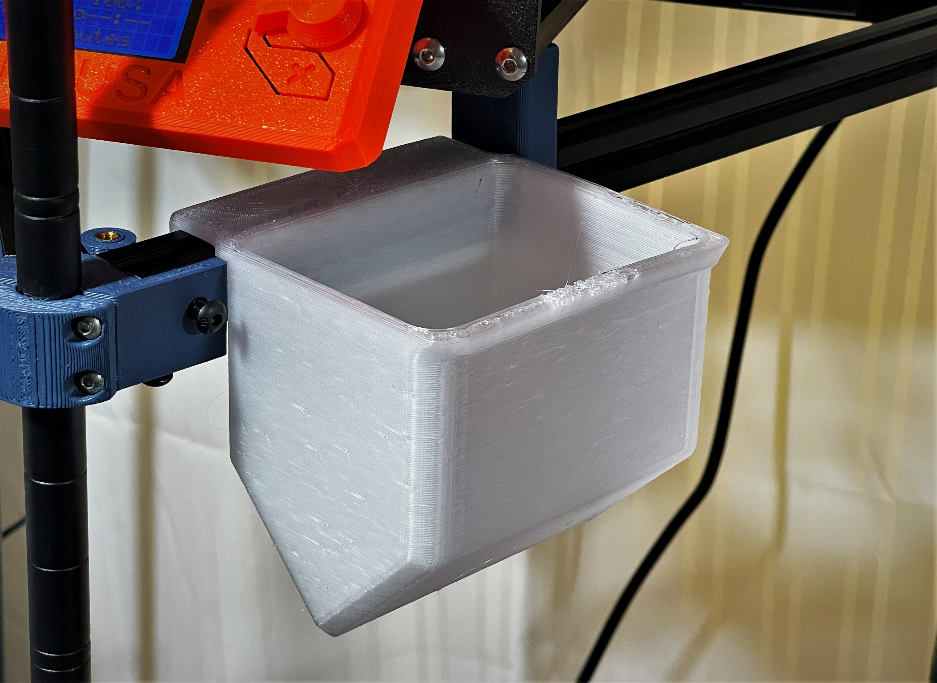 |
A simple waste bin that hangs from 2020 extrusion, intended as a convenient spot for tossing purge lines, brims, and the other assorted scraps/trash that accompany extrusion printing.
Prints without supports and took about 3.5 hours with the attached slicer config (0.6 nozzle), but I should point out that the lettering on my print came outa little lackluster.
I printed mine in Overture clear PETG
Simple Hook
A simple, quick-printing hook for hanging accessories and such from 2020 extrusions. I'm using several of them quite happily on my i3 printer tower.