A fellow Printables user recently asked me whether I thought any of my 2020 extrusion hinges would be suitable for use as the hinges for a folding table. I don’t think I would trust any of the ones I’ve made to date for this, plus, I figured a 90 degree locking mechanism would be pretty useful.
So I decided to take a stab at a hinge specifically designed for this use case.
 |
Update - Version 2
Build
BOM
- Printed Parts
- (Qty 1) Base.stl
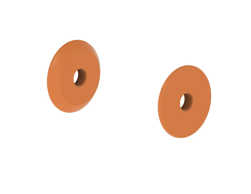
- (Qty 4) Bearing.stl*
- (Qty 1) LockPin.stl
- (Qty 1) Retainer.stl
- COTS
- (Qty 2) M5x20 BHCS - Down to 18mm length should be ok, but you want to be sure the fastener is bottoming out in the extrusion for the hinge to function properly.
- (Qty 2) M5 tee nut
- (Qty 8) 4mmx16mm Dowel pin - You can go longer, but shorter won't work well unless you're carful with how you press them. They are intended to bottom out at 10mm depth.
- (Qty 1) 2020 Extrusion leg - Leg length of your choice, but the longer, the wobblier :)
- Tools and such
- Sand paper - Small bit of sand paper to sand the bearings to fit. I used 120 grit. Aggressive enough to not take forever, but not so aggressive as to destroy my fingertips.
- Lubricant - Although not needed, some lubricant between the bearing interfaces should reduce the plastic-to-plastic adhesion and generally reduce wear.
- Two will need to be sized appropriately to fit. The other two are not particularly sensitive on their thickness.
 |
 |
 |
 |
Build
- Put the M5 BHCS through the outer bearing, flat side facing the head of the fastener
- Slide the fastener, with outer bearing along for the ride, through the hole in the Base
- Slide inner bearing onto fastener
- Repeat on other side
- Adjust both sides fasteners so that are flush, or slighly inset from the face of the inner bearing
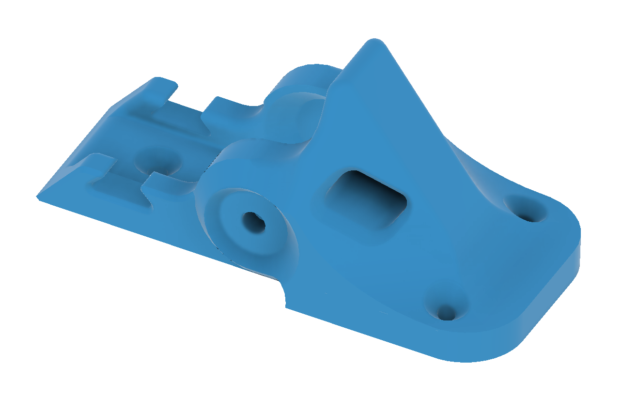
Design
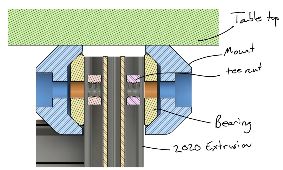
The general design concept for the hinge is similar to the others discussed on the 2020 Aluminum Extrusion stuff page. The cross-sections below show the basic makeup of the hinge and the intended load path. The printed 'bearing' pieces have spherical radii on the contacting surfaces, and these are mated with conical surfaces on the fixed mount (blue sections in the images.)
There is one major limitation for this revised design of the hinge, and that is due to the Mount part being a single printed component, whereas these outer races on my previous hinges were 'floating' relative to each other. This is a challenge cause it means the spacing that needs to be occupied by the extrusion and bearing is now fixed. I decided that the ease of install and improved part integrity offered by a single piece outweighed the impending assembly frustrations.
 |
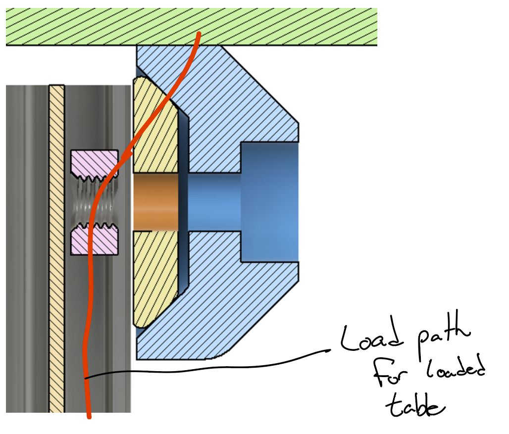 |
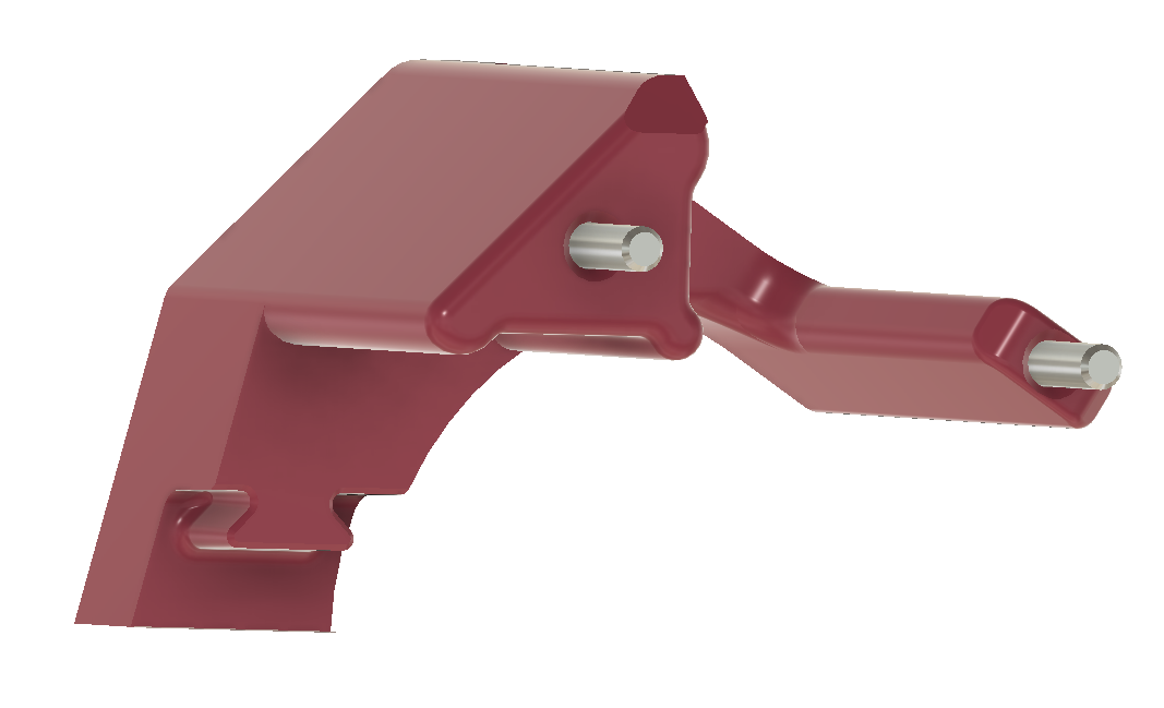
The fasteners (20mm long M5s) are threaded into tee nuts in the extrusion, and are driven all the way through to press against the extrusion. This keeps the stress in the bearing from being a function of how much the fastener is torqued and also keeps the fastener from loosening in operation.
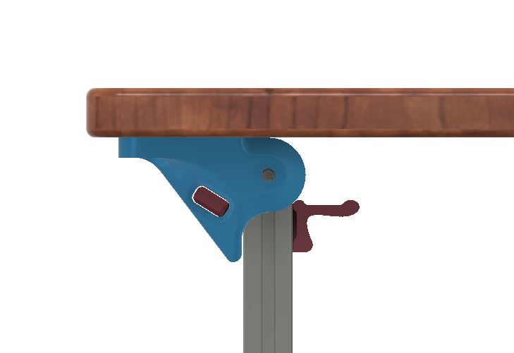
When folded, the table is intended to rest on a well-supported, rigid portion of the mount block. The goal here is to avoid unexpected storage loads from damaging the hinge mechanism or lock pin.
 |
 |
BOM
- Printed Parts
- (Qty 1) MountBlock.stl
- (Qty 2) Bearing.stl
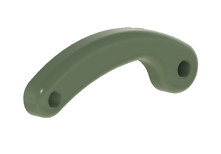
- (Qty 1) LockPin.stl
- COTS
- (Qty 2) M5x20 BHCS - Down to 18mm length should be ok, but you want to be sure the fastener is bottoming out in the extrusion for the hinge to function properly.
- (Qty 2) M5 tee nut
- (Qty 1) 2020 Extrusion leg - Leg length of your choice, but the longer, the wobblier :)
- Tools and such
- Sand paper - Small bit of sand paper to sand the bearings to fit. I used 120 grit. Aggressive enough to not take forever, but not so aggressive as to destroy my fingertips.
- Lubricant - Although not needed, some lubricant between the bearing interfaces should reduce the plastic-to-plastic adhesion and generally reduce wear.
Just can't get enough of my meandering design thoughts? Well you're in luck, I live-streamed the entire nearly 4 hour process of me designing this fella in Fusion360...I can't tell you this clearly enough, the value per unit time of watching is LOW :)
Build
The only part of this build that takes attention is fitting the bearings. It can require a bit of trial and error, but getting a good, secure fit here is very important to the hinge's performance.
The process I used was:
- Insert extra length M5 fasteners into the Mount Block. The extra length is just to make it easier to take them in and out during fit testing. I used some 30mm length SHCSs
- Slide bearings on to fasteners and retract fasteners until the end of the fastener is just slightly proud of the inner face of the bearing.
- Check fit. If you have calipers with long enough jaws, you can use calipers to measure the as-build gap. However, this is a bit tricky, as the bearing will want to rotate around on ya (damn spherical radius :) ). And/or you can just try to press in the extrusion section to check fit. Make sure that there are no burrs on the edges of the extrusion.
- Put sand paper on a flat, stable surface, and sand down the back face of each bearing. I sanded ~50um (.002") off for each cycle.
- Repeat 2-4 until you can insert the extrusion fully into the hinge. It should take a bit of force to insert, since you want preload in the bearing, but use your best judgement on how much force is too much force to avoid breaking the part and/or hurting yourself.
- Remove one fastener at a time, sliding a tee nut into position and securing one side before moving on to the other.
The Mount Block attaches to the table with two #6 wood screws (or at least that's what the holes were sized for.)
Lessons Learned / Recommendations for improvements
- Stiffening of the locking pin.
- Especially when in the storage state, but just in general I think it would be worthwhile to beef up this pin to make it both more rugged and more rigid.
- Might be nice to somehow integrate a cam-lock feature to actually put some preload into the joint when locked.
- Designing a single DOF compliance to the mount block to alleviate the tolerance stack/assembly challenges.