Wellllll….. :) While it manifested in a slightly different way than I expected, it was indeed the stiffness of the indicator flexures that was my undoing…but always a pleasant surprise to fail in an unexpected way! The issue ultimately was much more localized than I expected. The stiffness of the indicator flexures causes the leaf flexure to not give us the S-bend we are banking on…instead it essentially splits the leaf into TWO leaves, each one doin it’s own damn S-bend and keeping the center span level. I should point out that 1) I am exaggerating some in that last comment to paint a picture of the motion…did you see it? Was it pretty?…But anyway, because there is still a ratio of stiffnesses at play, there is still SOME deflection in the desired direction, but it’s very small. and 2) I should also clarify, that all of this is based only on visual observation of the deflection (aka, “I looked and squeezed”, but don’t worry, I did so a statistically significant number of times, I assure you) and back of the envelope analysis. So please feel free to correct me if you catch something I got wrong, but bring calcs….I never said it was fair ¯\(ツ)/¯
BubsBuilds Projects

- Details
- Parent Category: Just Playin and Concept Demo Projects
- Category: Flexure Fun


Objective
The general idea is for a flexure-based load cell design that utilizes the deflections within the flexural elements to mechanically display an indicator for the applied load.
The Concept
The idea is basically just for another ‘magnetically-assisted” flexure concept, but this one has pointers on it!!
For a first iteration, I was thinking I could just go with a compound flexure, (could even start with the Prusa Foot as a starting point) and put a pointer element at the mid-span on the leaf flexures. That should be the point with the highest angle of deflection.
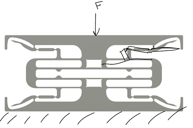
Below is the ‘hammock sketch’ that got the ball rolling on this one. However, there is a critical flaw in the design as shown in the sketch….can you see what I F’d up? :)
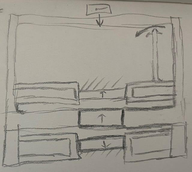
No? Fair enough, it’s hard enough to even tell what the hell I was trying to draw :D The problem is that, as depicted in the sketch, the flexure is over-constrained. This configuration of flexure is, more or less, a set of four individual ‘four link’ mechanisms. If you think of a conventional four link, one side stays fixed, and the free side maintains its relative orientation, but it’s center travels along an arc, as shown in the child’s sketch below.
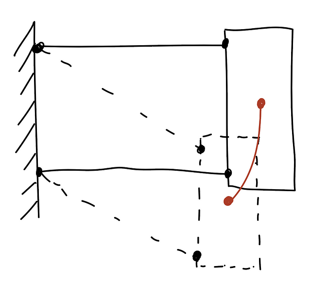
And it is this arc that is source of the flaw in the sketch up top. In that design, neither the fixed sides (here shown as the top and bottom magnet pockets, both are anchored to ground), nor the moving side (attached to the moving table) have freedom of motion to allow for the relative lateral (if looking at the four bar linkage sketch) translation of the elements through the flexure’s travel.
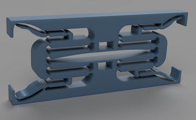
But anywho, the below images give a little better overview of the concept (I think/hope).
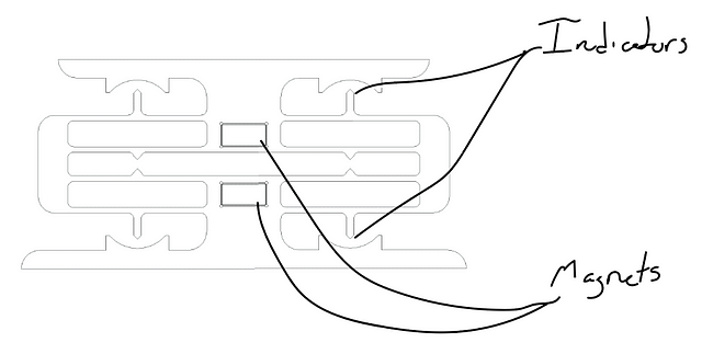
There are two magnets, one on each side of a symmetrical flexure. The magnets are oriented such that they repel each other, providing the bulk of the total stiffness in the direction of motion/measurement
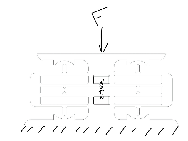
As the flexures deflect, the ‘leafs’ will deflect into S-bends, with the midspan having the maximum angular deflection along the span. So it’s at that midspan point that we’ll add our little pointers! More info on the specifics of this design below under Rev 1.
Rev 1 Design
So here is what I cooked up as a quick proof of concept test design (yeah, I used this for the overview, so not really much of a reveal). Each of the magnet pockets measures 12(W)x6(H)x12(D), intended for Four (4) 12x3x6 magnets in each pocket (so eight magnets total).
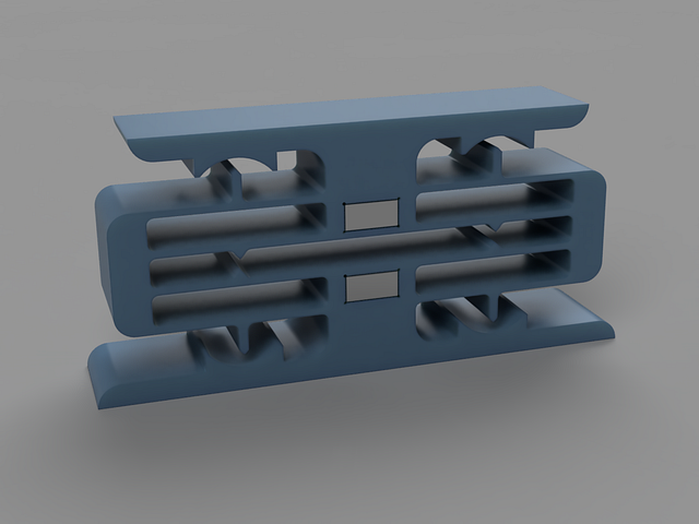
One thing that might stand out with this design is that I’ve added pointers in far more locations than seems needed (or even reasonable), but it is VERY important for this flexure design to try to maintain symmetry as much as possible to provide the most linear motion profile (and therefore most accurate load measurement….although less crucial for this particular one I guess….but hey, I like symmetry anyway)
Concerns
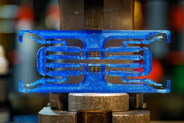
My main concern with this design is that the deflection will be too small to give a reasonable “signal to noise” on the indicators. While I could calculate this angle, I honestly just don’t feel like it and want to submit this design for the Printables contest ending today ¯\(ツ)/¯ So instead I’m gonna just go for it and print one out! I shall report back (maybe)
Results
Yeah…..that concern was true :)….don’t you DARE point out my “could calculate it” comment….
I’m still actually pretty happy with it, in that it does still demonstrate what I was hoping to see. But I did move on pretty quickly to Rev2 :)
If you want to test it out yourself, you can find it on Printables
Rev 2
As feared, Rev 1 didn’t have quite the deflection one might desire to be even moderately useful :)
Enter Rev 2! But how to up the measurement deflection? Why, more flexures of course!
I replaced the pointers with linkages to some notch-type flexures to give a mechanical amplification (aka ‘lever’ )

The below shows….kinda….the expected deflection profile. As you can see (hopefully), the ‘pointer’ from the Rev1 design ‘pulls’ the linkage in toward the center. On the other side of the linkage is another notch flexure connected to the rigid frame element on top. If you aren’t familiar with notch flexures, they act (to first order) like a rotational hinge with the pivot point at the center of the thinnest portion of the notch. So this end of the linkage will be rotated around this pivot point, and so will its rigidly attached pointy end! So the tip of the pointers should rotate about their flexure center pivots. The movement of the pointer will be equal to movement of the linkage multiplied by the ratio of the Pointer Radius : Linkage Radius, which I configured here to be 8:1. So that SHOULD mean that what we have is essentially an 8x ‘gain’ on our sensor! :)
Concerns
So, what could go wrong? My main concern with this one is that the indicator linkages and their associated flexures are too large of a portion of the total stiffness of the mechanism. There is also an imbalance in stiffness between the “inner” and “outer” flexure sets. My concern is that these effects may now be significant enough to cause issues. The best way to address this would be to 1) drastically reduce the stiffness of the indicator flexures relative to the ‘main’ flexures, and 2) compensate the ‘inner’ flexures’ stiffness to compensate for the parasitics caused by the indicators. Instead of adding some sort of mirrored flexure set, I would probably just calculate the appropriate change to the thicknesses and or lengths of these leafs such that their effective stiffness matches the effective stiffness of the full set of stuff goin on with the others.
But alas….I am already designing these flexure webs at about the limit of thinness that I’m comfortable with printing for these quick test/concept prints. And I don’t want to increase the main flexure stiffness because a key aspect of this concept is maintaining the magnets as the dominant source of stiffness in the direction of measurement. And for the latter….I just don’t feel like it. While I very much enjoy playing with these, I don’t know that I like it enough to do ‘real work’ :)
If you DO want to calculate optimal flexure parameters (or at least a rough estimate….the anisotropy of printed parts breaks a pretty good set of assumptions in most of equations) this book is my absolute go to for such things. Or, if you want to go hardcore and even build the model to account for the printed materials, you could give this one a go :). While I do own both, I honestly pretty rarely open the second (sorry Stuart!)
Results
Rev2b
Not a ton changed here. I swapped out the leaf springs for a collection of notch flexures. Little aside, but this is actually more in line with how I would generally design this type of flexure ‘for real’, or at least it would be for a metal flexure being traditionally machined. Notch flexures are MUCH easier to machine than leaf flexures, unless you are fortunate enough to have a Wire EDM machine with some downtime :).
By moving to notch flexures, the midspans are now rigid bodies (or at least can be assumed as such for our purposes here). So this will provide a much more predictable deflection for our indicators.

Concerns
My general concerns from before about flexure performance degradation caused by the interplay of the indicator flexures and main flexures remain, but not significant for the purpose here (if I were trying to build a positioning system, for example, this would be a MUCH bigger concern, since my assumption is that this will primarily present as parasitic motion(s).)
The only new concern that I have added for myself here is related to the clearance cuts I had to add in the center to keep the inner flexure bodies from reducing our range of travel. The problem that this presents is in how it will impact the location of the pivot points for those hinges. Any asymmetry within a notch flexure will impact where the center of rotation lands for that flexure. If you go back to the four link discussion up top, you may see that having the arms of the four link being the same length is critical for that mechanism to give the motion profile we’re aiming for (fun aside, but you can also use this “problem” to your advantage by introducing a prescribed rotational motion by intentionally varying these lengths.) And so here in lies my concern. The movement of the inner flexures pivot locations due to the asymmetry means that the inner and outer links will have different arm lengths…not ideal! My assumption is that the amount of deviation in axis location for this specific asymmetry isn’t going to move the rotation axis any more than my manufacturing tolerances already are. The basis for this assumption is that the amount of asymmetry of the notch along the axis that we’re most sensitive to (left-right on the above image) is very low. There is significant asymmetry on the other axis, however, this will just cause the pivots to move in a direction that does not impact our performance here.
Results
Well, if you saw the gifs up top, you get the gist :) This one basically demonstrates exactly what I was hoping! So at this point, I’m going to call this series done, at least for the time being. Happy to hear ideas for improvements, questions, or whatever else ya think may be of interest!
- Details
- Parent Category: Just Playin and Concept Demo Projects
- Category: Print-in-Place Designs
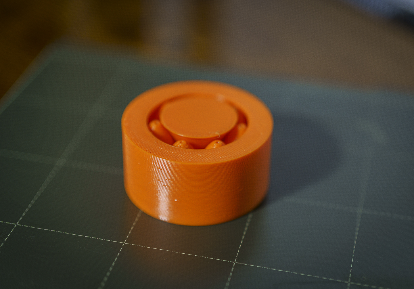
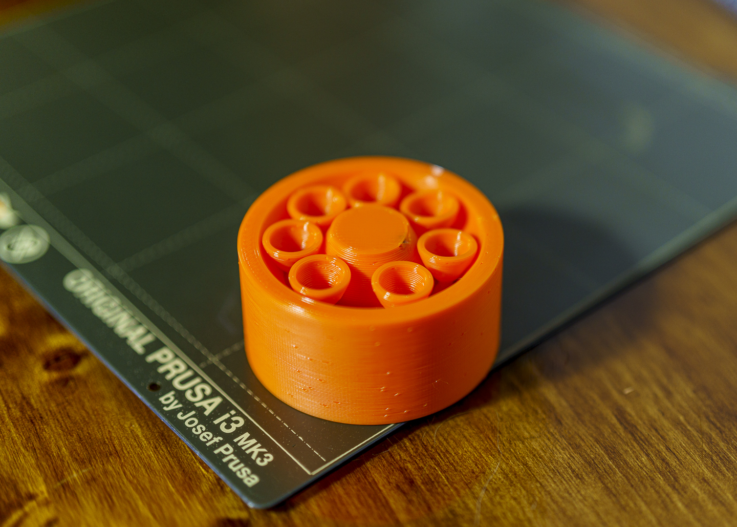
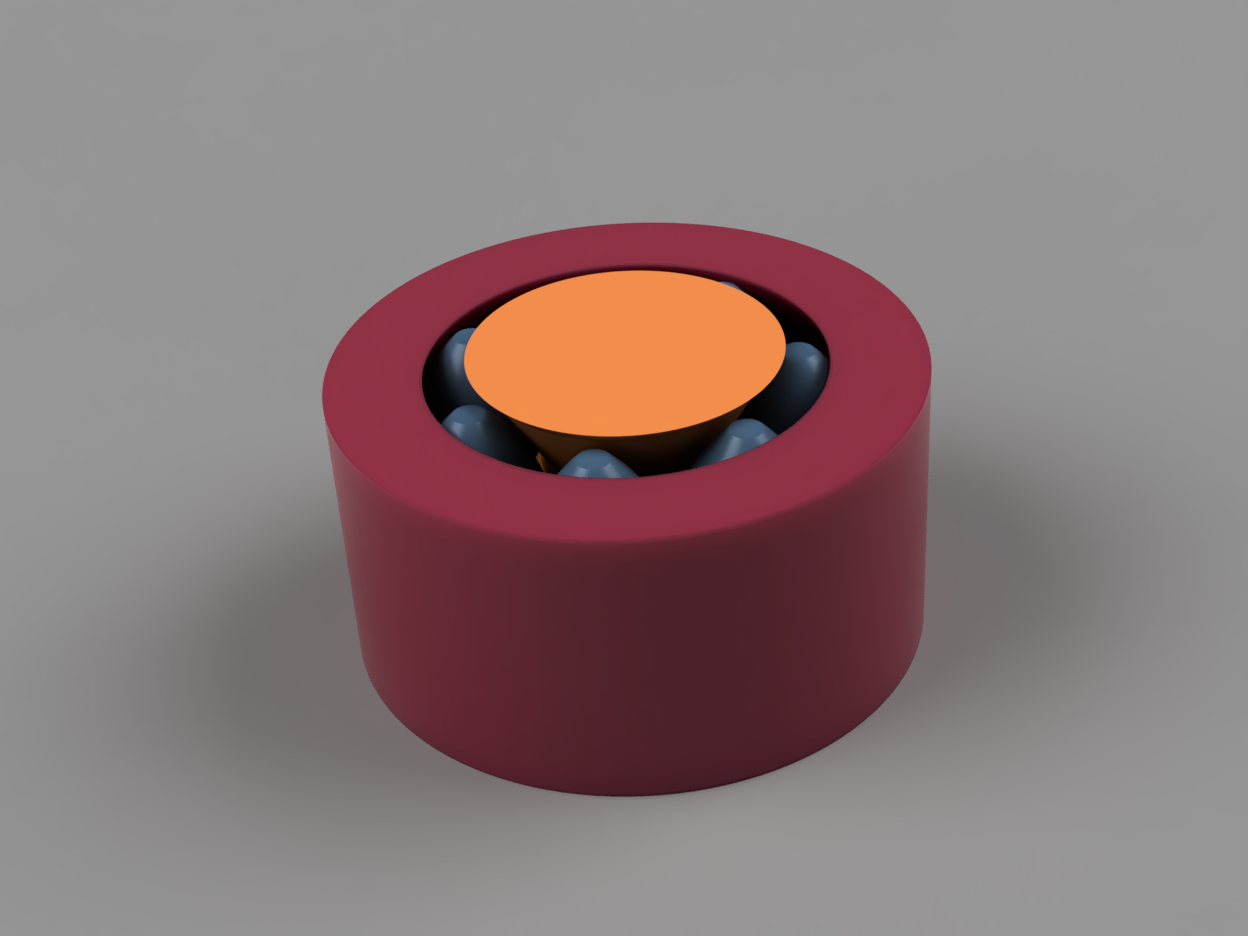
Roller Bearing
|
|
 |
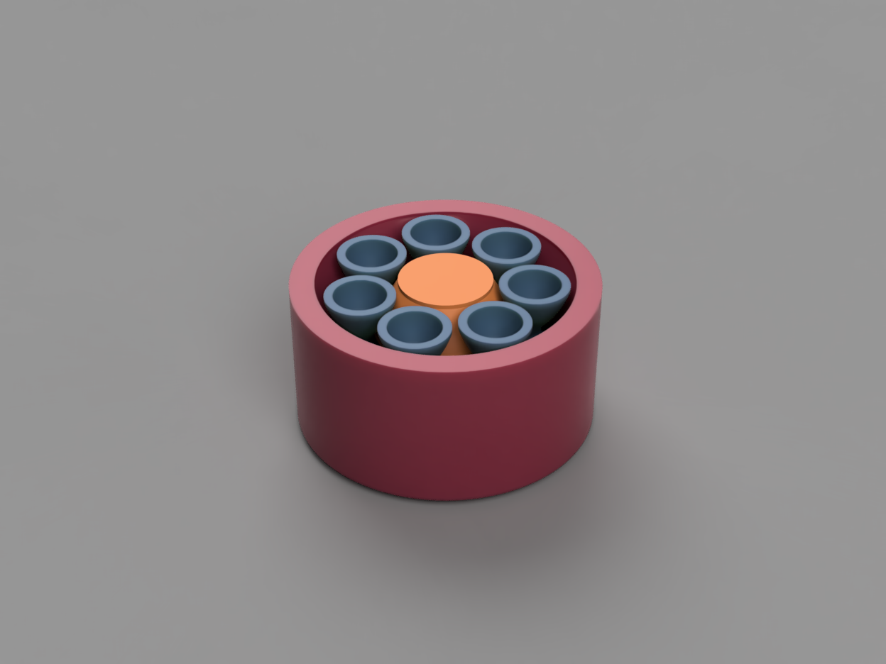 |
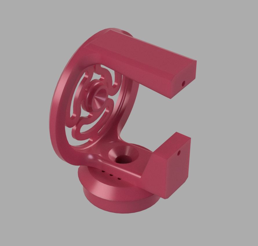
A print-in-place rolling element bearing. I've got some plans for incorporating this concept into a bigger project, but I think bearing came out as a fun little desk toy/fidget toy in its own right! (at least to me :) )
Print should not require any supports, brims, etc. I printed the one pictured coarsely with a 0.6 nozzle @ 0.48 layers in PETG.
I think I was a bit too conservative on the clearances for the rolling elements, but she holds together and rolls pretty well! I've got some ideas for things I want to experiment with to get a preload into the bearing. So hopefully there will be some fun follow-ups coming soon
- Details
- Parent Category: BubsBuilds Projects
- Category: Pet Stuff
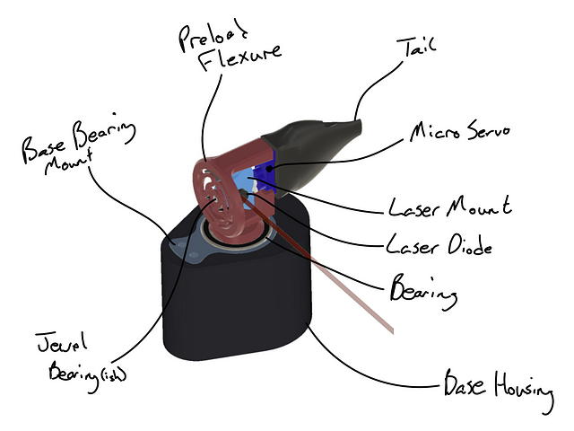
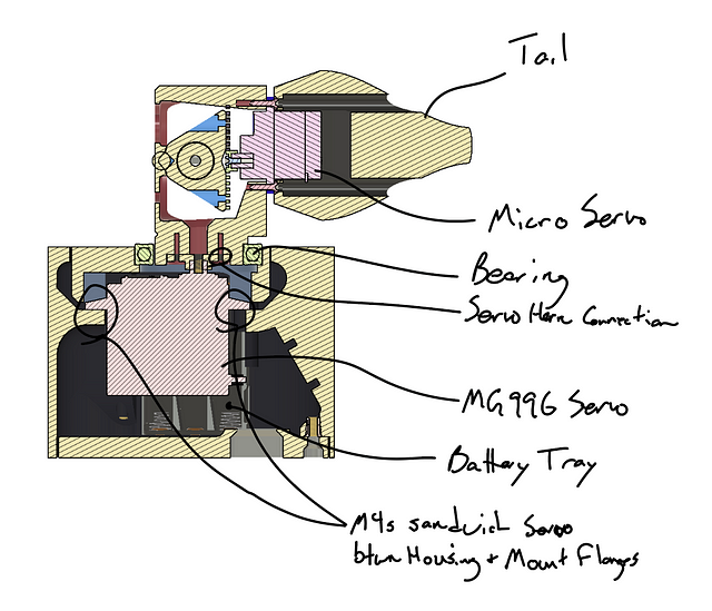
It’s an automated cat torture device! Ok, not exactly, it’s a 2-axis turret with a cheapo laser pointer mounted in it, run off of a budget microcontroller :) But as shown in the little clip below, my little dude finds it quite entertaining (I actually have to hide it in a drawer if I’m not letting him play with it…I’m actually working on an idea for an upgraded version that I hope will help with this, but who knows if I’ll actually get to it ¯\(ツ)/¯)
*If you have any questions or if you want to cast a vote for me to write up a detailed assembly how-to, drop me a comment!
BOM
Printed Parts
- Base_Housing (heatsets)
- Base_Lid
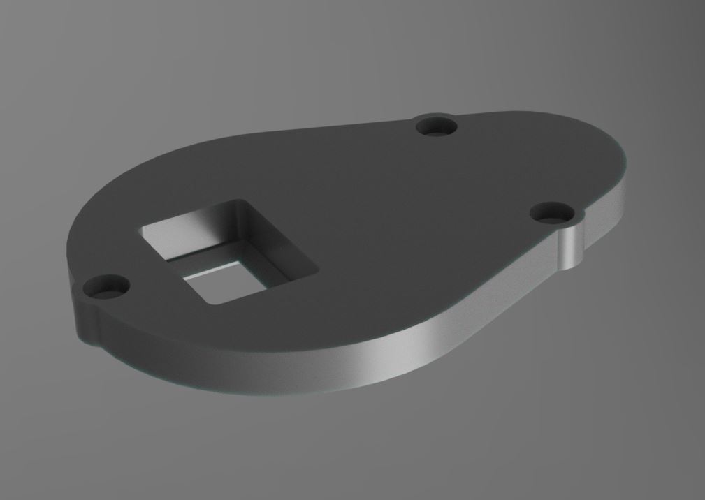
- Base_BearingMount
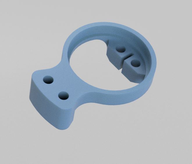
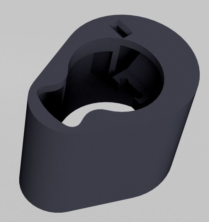
- LaserMount
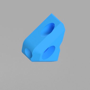
- PreloadFlexure
- Tail (optional)
Purchased/COTS Parts
- SG90 Micro Servo — I have bought this 10 pack twice now, but obviously for this project you’ll only need one (I just can’t resist me a bulk discount on motors :) ). Any SG90 Micro Servo should work just fine.
- MG996R Servo — Again, this is the multi-pack that I have bought a couple of times now. Of the twelve servos in those, I’ve had one break….but I hesitate to blame the servo on that one…tee hee ¯\(ツ)/¯
- Kitty laser pointer — Unfortunately on this one, you would likely need to make your own custom “LaserMount” part if you go with an alternative option. Any laser pointer should work, but just keep in mind that you will want one that you can somehow commandeer from a microcontroller if you want the fully automated ability. NOTE: While you don’t HAVE to get this hot pink one….you CAN….just sayin
- 6806–2RS Bearing — I’ve been absolutely loving using these large ID bearings for servo-driven projects lately. So damn convenient being able to just run the horn right up the middle! That being said, you definitely don’t need 10 of them if you aren’t going to make use of them elsewhere. So any 6806–2RS is fine (really you can probably get away with any bushing/bearing that’s 30x42x7mm given the low loads, but I personally think it’s worth the couple of bucks for that buttery smoothness :)
- 3xAAA Battery Holder — Ok…so I feel a smidge bad about this one….the battery trays I used for this are ones I bought from a Radioshack going out of business…I told you! I’m a sucker for a bulk discount!!…But these are the same type of 3-battery, plastic tray with leads. If anyone tries these and they don’t fit, or if there is some awesome battery holder out there, please do let me know and I will update this accordingly.
- Seeeduino Xiao — This project was my first time working with the Xiao, and I’m immediately a fan! I continue to be amazed at the power per dollar of microcontrollers hitting the market, and in a tiny form factor, and supporting Arduino and MicroPython…just delightful… But anyway, while I went with the Xiao, at a minimum you really just need two PWM outputs to give the servos their position duty cycle (and I’d recommend another I/O for on/off, but your call if you prefer minimalist).
- Heat Set Inserts — I used Three (3) — M3x6 and Four (4) — M4x8 heat set inserts. You can safely go a couple of millimeters longer or shorter for either without issue. The link is to an assorted pack that I have and really like (although it has long been emptied of any M3s or M4s). If you would like some additional info on heat sets, I’ve started jotting some additional notes here also.
- ON/OFF Switch — This is the one that I sized the hole for in the Base_Lid, but there are tons of options in this size range if you switch-specific.
- Transistor for switching ‘da laser — Now we’re getting in to territory where I don’t feel like I should be making recommendations :) I know how to make these things work (usually), but I really can’t say enough how much I’m not an electrical engineer….or even a particularly good mechanica….huh? but seriously, this is what I used and it works, but I’m all ears for anyone pointing out better approaches for this stuff!
- Breadboard — I used this lil feller to tie the room together
Code
I will never pretend to be a competent programmer, so please feel free to talk s*** on my code, but I will say, I was actually kinda proud of the randomization routine I cooked up :)
My apologies for the lack of annotation, but I originally didn’t intend it for others’ eyes (and still am not sure it will see any, haha). But I’m more than happy to answer questions if you reach out to me
#include <Servo.h>;
Servo serRot;
Servo serEl;

int pinRot = 7;
int pinEl = 10;
int pinLas = 5;
int minEl = 60;
int maxEl = 90;
int minRot = 90;
int maxRot = 180;
int nseqEl, nseqRot;
int iseqEl = 0;
int iseqRot = 0;
int stepEl, stepRot;
int signRot, signEl;
int posRot, posEl;


void setup() {
  pinMode(pinLas, OUTPUT);
  pinMode(pinRot, OUTPUT);
  pinMode(pinEl, OUTPUT);
  serRot.attach(pinRot);
  delay(50);
  posRot = (minRot+maxRot)/2;
  serRot.write(posRot);
  delay(100);
  serEl.attach(pinEl);
  delay(50);
  posEl = (minEl+maxEl)/2;
  serEl.write(posEl);
  delay(500);
  nseqRot = random(5, 30);
  nseqEl = random(1, 10);
  signRot = random(0, 1); // Sign = 0 = increasing angle
  signEl = random(0, 1);
  stepRot = random(1, 5);
  stepEl = random(1, 3);
  digitalWrite(pinLas, HIGH);

}

void loop() {
  // Calc next Rot position
  if (signRot == 0) {
    posRot = posRot + stepRot;
    if (posRot > maxRot) {
      posRot = posRot - (2 * stepRot);
      signRot = 1;
    }

  } else if (signRot == 1) {
    posRot = posRot - stepRot;
    if (posRot < minRot) {
      posRot = posRot + (2 * stepRot);
      signRot = 0;
    }
  }
  iseqRot = iseqRot + 1;
  if (iseqRot > nseqRot) {
    nseqRot = random(5, 30);
    posRot = random(minRot, maxRot);
    signRot = random(0, 1);
    iseqRot = 0;
  }
  serRot.write(posRot);

  // Calc next El position
  if (signEl == 0) {
    posEl = posEl + stepEl;
    if (posEl > maxEl) {
      posEl = posEl - (2 * stepEl);
      signEl = 1;
    }

  } else if (signEl == 1) {
    posEl = posEl - stepEl;
    if (posEl < minEl) {
      posEl = posEl + (2 * stepEl);
      signEl = 0;
    }
  }
  iseqEl = iseqEl + 1;
  if (iseqEl > nseqEl) {
    nseqEl = random(1, 10);
    posEl = random(minEl, maxEl);
    signEl = random(0, 1);
    iseqEl = 0;
  }
  serEl.write(posEl);
  delay(random(1,400));

}
Subcategories
Assorted (hopefully) "Useful Stuff" Projects Article Count: 12
Like the bucket of assorted fasteners on that bottom shelf, this category is for stuff that I didn't know how to group...oh, and speaking of those fasteners, check out the little sortin fella!
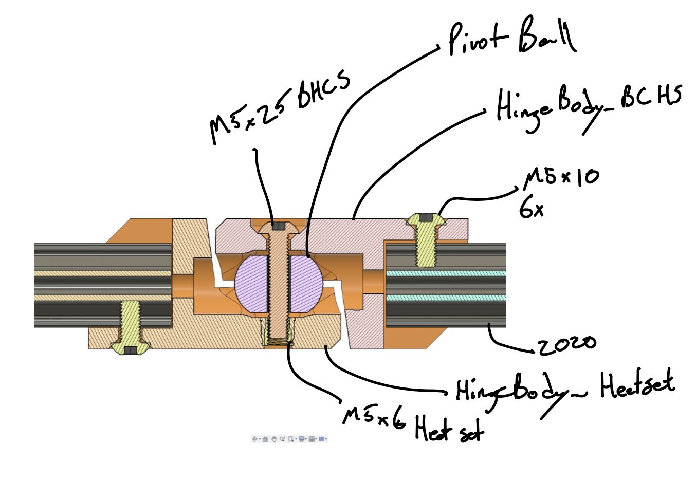
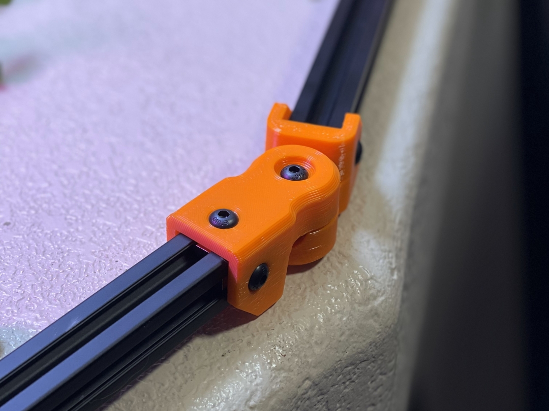
2020 Aluminum Extrusion Hardware
|
Quick Bolt Sorter
|

General Purpose Turntable - Gen1
Games Article Count: 1
Generative Design Projects Article Count: 3
During the good financial decision-making times of Covid lockdowns, etc. I decided it was a good idea to buy a license for the Fusion360 Generative Design extension...Good news, I did finally pay that off :) I had worked around, and been somewhat involved in a handful of Topology Optimization/Generative Design projects through my work, and I've found the tech super interesting for some time. So after the free trial, and feeling like I was just starting to gain some level of competence in Fusion360's tool....I done did it, and bought the year. Ok, now that I'm done justifying that to myself...I mean you...
<engineering/design> What I really like about Generative Design is that it forces the designer to think about the thing they are trying to design from it's core requirements: Forces, Interfaces, and Keep Outs. I think it's far from perfect, especially given the still very primitive Design For Manufacture capabilities these tools have (among other shortcomings, but this one is certainly a big one to me.)
<precision engineering> One last also (for now), but ALSO, what I find exciting about these tools from a precision engineering perspective, is that the above-mentioned focus on forces and interfaces, these tools are extremely well-suited to kinematic/exact constraint designs! I think every one of the Generative Design projects below features at least some aspects of kinematic constraint (I say, "I think" because I may or may not be writing this before I go through my files and remind myself what all I actually made vs what I just thought about making ¯\_(ツ)_/¯ )
JFS Projects Article Count: 14
AgTech (aka finding a way to complicate and digitize gardening) Projects Article Count: 12
Hydration and Hydroponics Projects Article Count: 8
Peristaltic Pumpin Article Count: 4
A lot of projects I work on/have worked on seem to involve the controlled movement of fluids. Below is a bit of a history of my builds involving attempts at obtaining this controlled movement for incompressible fluids. I haven’t done much myself with making custom solutions for the compressible stuff, but if you’re interested in such things, I thoroughly enjoy Major Hardware’s “Fan Showdown” series :)
This article/section is by no means intended as a thorough overview on the design and operation of pumps. While I will try to give some overview on operating principles and design considerations as I go, this is mainly just going to be a wander through my personal builds and experiences.
Peristaltic Pumps
What is a peristaltic pump?
I’m sure there are innumerable sources online for (much better) detailed discussions of the workings of peristaltic pumps. So I’m just going to hit the highlights, and I’ll try to remember to find some promising links and add them below, should a deep dive seem intriguing to ya.
Basic Operation:
The fluid being pumped is carried into the pump in a compliant tubing. This tube is routed around some portion of a circular/cylindrical path around the axis of the pump and then exits the pump. This is one interesting/attractive aspect of peristaltic pumps, the fluid never has to leave the tube that it is in, making these pumps well-suited to situations where contamination and/or leaks are highly undesirable. The housing that features the cylindrical wall that the tubing is being routed along can be considered the Stator, and that is generally the nomenclature that I tend to use.

So if there’s a Stator, there must be a Rotor…? Yup, the rotor includes some set of features that extend out to some defined gap between this feature and the Stator wall. These features, which in many peristaltic pumps are rolling element bearings, pinch the tubing to the point of sealing (ideally) the tube. As the rotor turns, this contact point proceeds around the circumference. Because the pinched point of the tube is sealed, the volume of fluid in the tube ‘ahead’ of the pinch point are, as a result, pushed forward. So, keep rotating, keep pushing….pretty much as simple as that!
Pros:
- Positive Displacement Pump
- Because the pinch point is (ideally) fully sealing the tubing, the amount of fluid moved is directly proportional to the movement of the pump. This makes them very good choices for things like dosing pumps or other applications where the desired volume of fluid to be moved needs to be deterministic.
- This is a large driver for my initial interest in using peristaltic pumps. Their deterministic flow is/was very attractive for my plant growth experiments. They can give very repeatable watering volumes and nutrient concentrations.
- Fluid Isolation
- Because the fluid never leaves the tubing, these pumps can be suitable for moving hazardous materials. For example, I have been using a peristaltic pump for transferring 99% IPA
- Relatively Simple Construction
- Because the fluid does not have to be sealed within the pump, these pumps lend themselves well to DIY builds. No shaft seals, gaskets, etc. or complex (at least to do well) impeller design needed.
- Self-priming and Head height
- If well-sealed, these pumps are capable of self-priming (and even pumping air) and of achieving pretty impressive head heights (the measure of how high above the pump it can pump a column of water)
Cons:
- High drive torque
- Because of the preloading needed against the tubing, and the rolling friction, even with good rolling elements (more below on this), it can be quite easy to end up with designs that require quite a lot of drive toque.
- Tubing wear
- With the relatively large deformation and high number of cycles, the tubing will eventually fail, either due to material wear, fatigue cracking, or who knows what else. Because this failure mode can cause fluids leaking into your pump not designed to experience this fluid, this failure can potentially be quite problematic. So the use of high-quality tubing material and a plan for periodic maintenance, are worthwhile.
Test Build 1
A couple of years back, I had a concept for an in-line-mixing hydroponics system. The idea being that the supplies to the system would be just pure water and nutrient concentrates, and a series of pumps and valves would allow precise dosing mixes to each target plant in a system (I refer to this concept as Rail Yard Hydro, since it moves the fluids around the tubing network quite like rail cars are moved around a rail system. I’m planning to add a separate page diving into that one a bit deeper since it is the design scheme I am using in my current projects.)
Well, to facilitate this plan, I wanted to find an option for a dosing pump that I could integrate in to my control system (aka Arduinos and Raspberry Pi’s :)). Unfortunately, I quickly found that a servo-driven peristaltic pump could easily set me back north of $100….so I set out to spend many multiples of that making my own!
Actually, when I saw the pricing, I decided I should see if I could make myself a cheapo, manual version that I could use to just test out some basic questions on the Rail Hydro idea (mainly verifying that I could induce good material mixing in-line and that there was no cross-contamination between fluid reservoirs.) And so, ‘twas this endeavor that resulted in the pump I’m apparently referring to as “Test Build 1”
Design Objectives:
- Be a peristaltic pump
- Provide a full seal (at 100mm head)
- Be hand-cranked
- Not require any parts that would have to be ordered (I’m impatient)
The Build
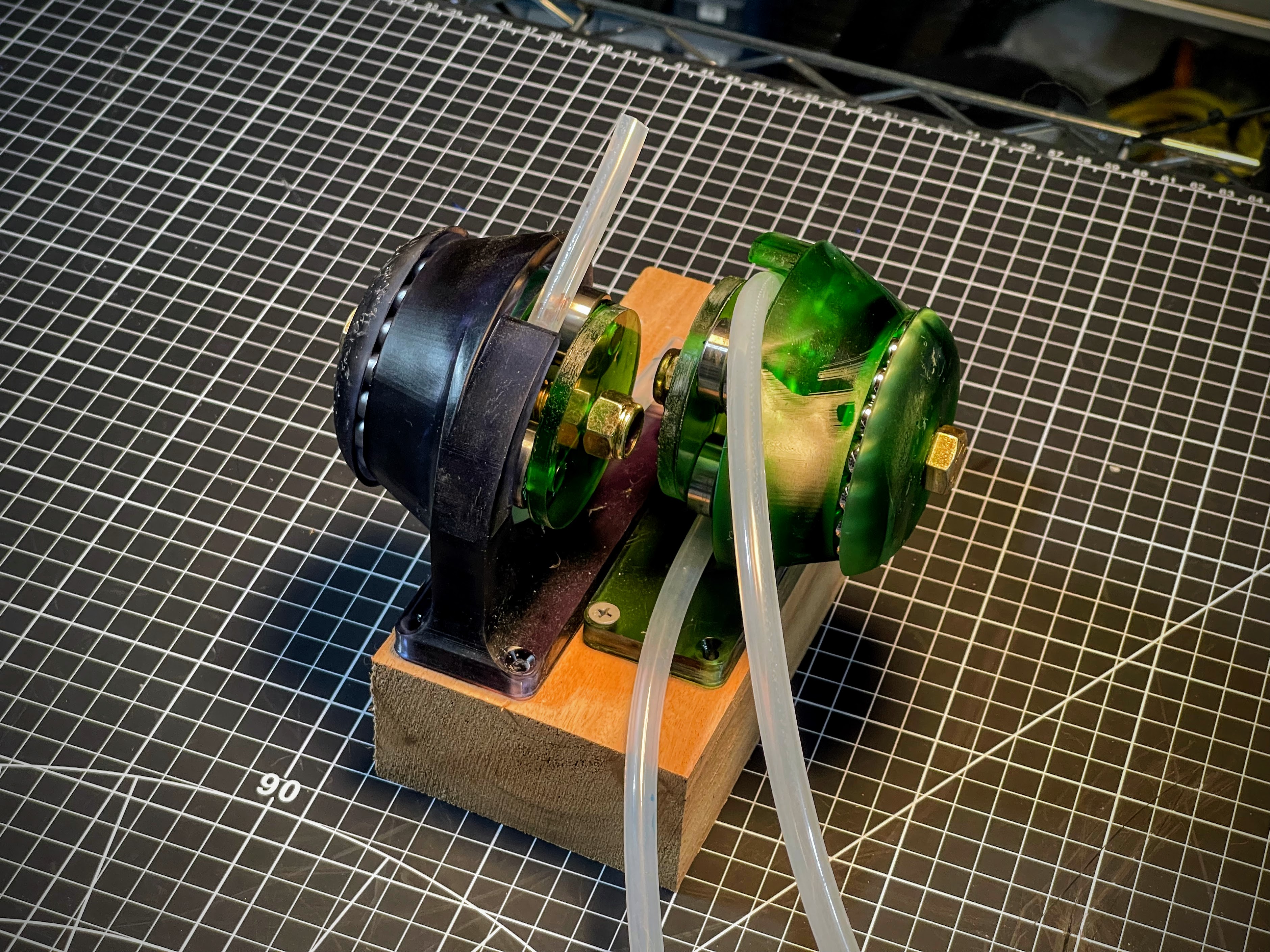
She ain't pretty (especially after a good while of getting knocked around), but the pic above shows the dual pump setup I rigged up for my testing needs. I was VERY pleasantly surprised that, other than a tweak to the hand wheel, these things worked pretty damn well!

I decided upfront that I was going to go with a resin printed build, because I thought the high stiffness and good surface finish throughout the 'pinch region' would give me a better chance. Since I was already going to have the good surface roughness, I might as well also integrate the main bearing into the printed parts.
In the image of the model, below, the Stator is the part shown in green, and the Rotor is shown in blue(ish.) Riding on the rotor are roller skate bearings to provide the contact with the tube. Race 1 has v-grooves on both sides of the race, providing the main constraint for locating the rotor, and Race 2 has a v-groove on the Stator, but only a single plane of contact on the Rotor side. This keeps from over-constraining the bearing.
 |
 |
The absurdly overkill bolt running through the center is a real showcase of "using what I had on hand" :) in that these were the only bolt/nut sets I had on hand with the length I was looking for.