I know there are tons of designs out there for spool holders...yeah, pretty much just that. No clue why I decided I I needed to add my take on it, but alas, here we are.
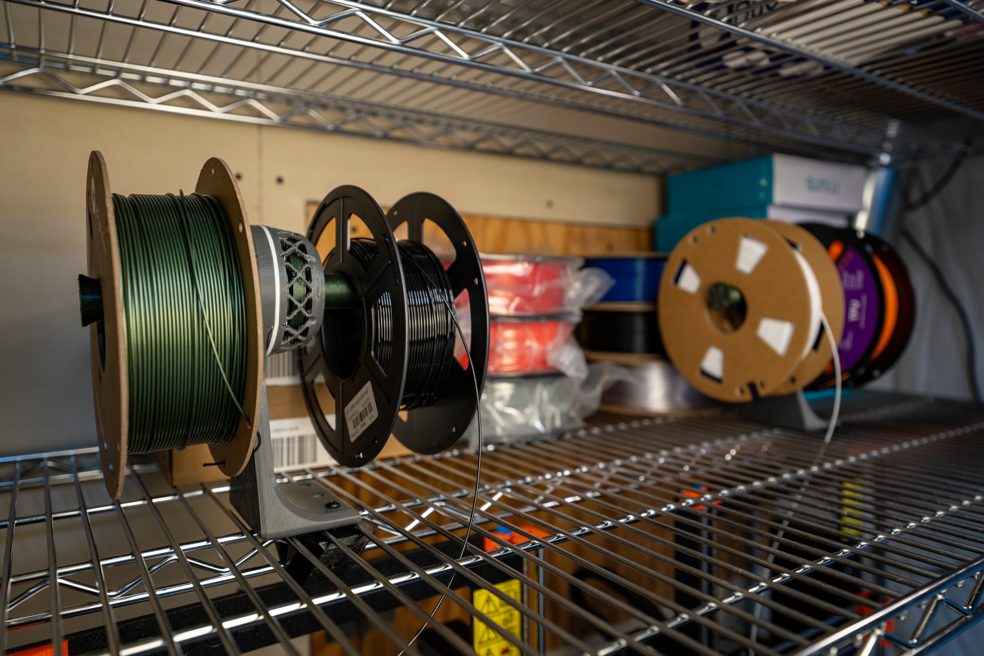
I recently rearranged my printer setup to move all of my filament printers only a single wire shelf (I say "all", it's 3, which is a lot to me, but I know, not exactly a print farm :) ). My two Prusa Mk3ses fit on one shelf, and the monster (aka Elegoo Neptune 4 Max) takes up another. Although I had the vertical space to just have the shelves spaced far enough apart to fit the OEM spool holders, I thought it would be preferable to have a single "filament shelf" and then route filament from there to the printer. This would allow me in the future to enclose that shelf as a large dry box/dryer as well as keeping filament nice and centralized. All them eggs in one spot where I can see 'em!
Design Overview
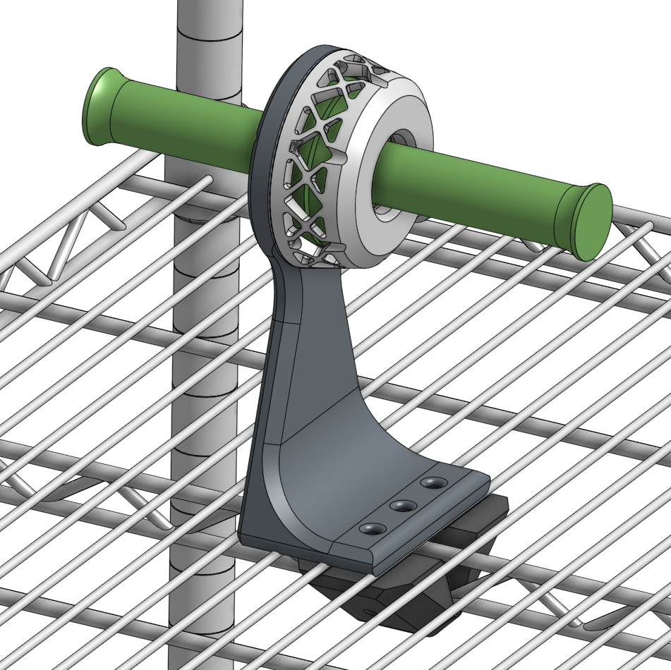
The main structure of the spool holder is provided by the 'Mount Race' part. It secures to the wire shelves with the Cap with two M5 heat sets. The Cap is intended to straddle the central brace that runs along the length of the shelf to provide resistance against rotation.

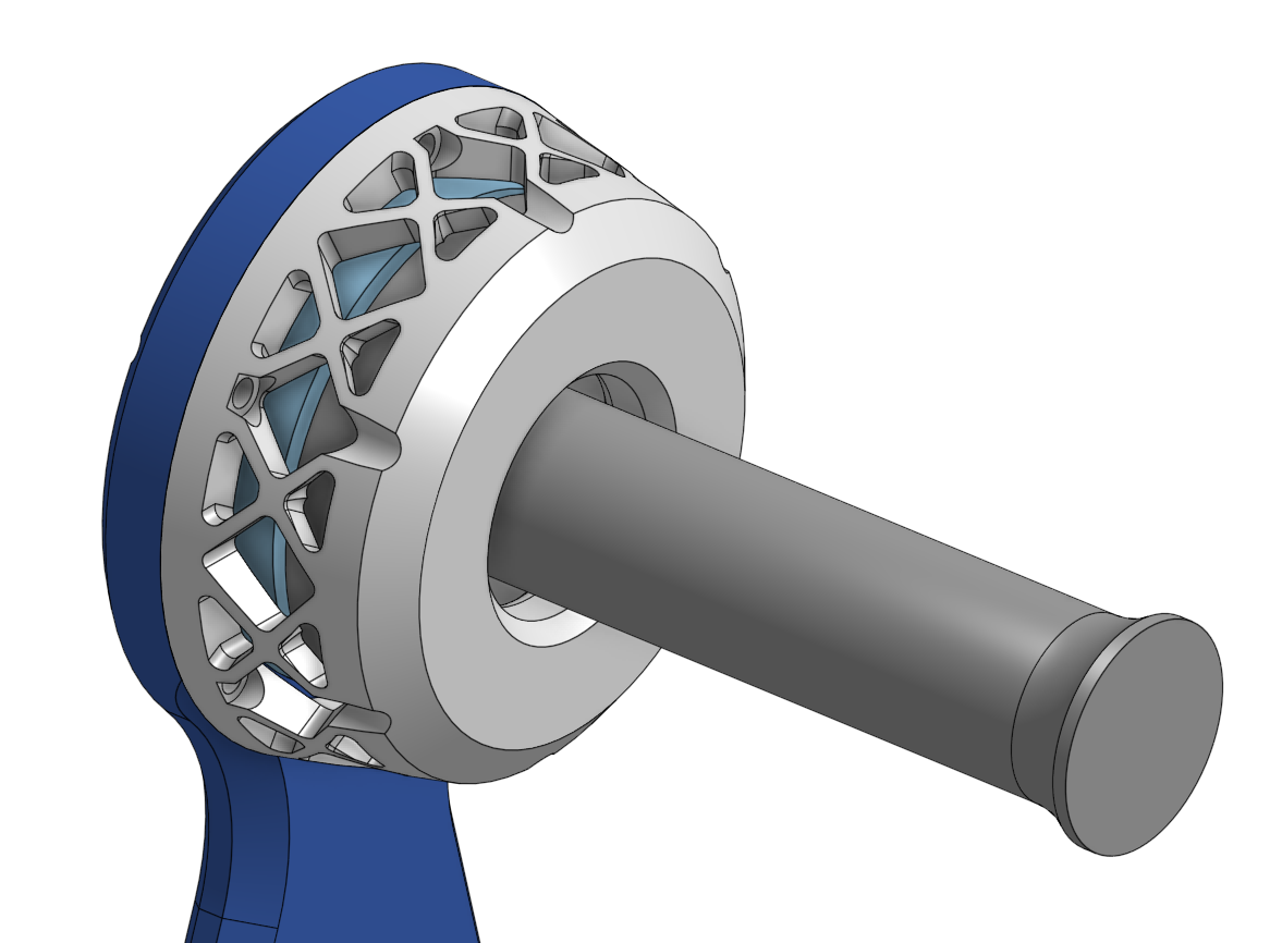
The 'race' aspect of the Mount Race comes in the form of a v-groove that runs circumferentially around the rim. It is filled with 16 bearing balls and mated with a matching groove in either a Spool Blank or Spool Post.
Another Spool Post is then mirrored on the first with a single ball making a "jewel bearing". This jewel bearing serves two purposes. The first is that it allows the two spools to spin independently, and the second is that it allows for angular misalignment between the Mount Race and Retainer Race.
Speaking of the Retainer Race, it sits on top of another 16 balls in the top of the race of the Spool Post. It is secured to the Mount Race with six M3s, with heat sets inserted into the perimeter of the Mount Race.
The result is that the load from the left spool is transmitted directly into the rigid mount via the bearing. The load from the right spool passes through the Retainer and throught the bolted flange to the rigid Mount Race.
CAD: If you want to dive into the dumpster fire of a CAD model yourself, you can find it on OnShape here.
Build
BOM
- Printed
- (1) MountRace - Mostly Sunlu PETG, with a touch of green Polymaker PETG on the base
- (1) RetainerRace - White Sunlu PETG
- (1) Cap - Black Sunlu PETG
- (1 or 2) SpoolPost - Green Polymaker PETG
- (0 or 1) SpoolBlank - Only needed if using for a single spool. Shown in the gif above. Green Polymaker PETG
- (?) Spacers - The number and thickness of spacers depends on how much preload you want to put in your bearing.
- COTS
- (33) 9.5mm balls - 16 in each race and one for the center 'jewel bearing'. I actually use 3/8" 'slingshot ammo', but it's technically modeled for 9.5mm...close enough :)
- (6) M3 heat set insert - I went with 6mm lengths. Anything up to 10 should be fine.
- (6) M3 BHCS - Length will depend on spacers, but likely between 10 and 12 mm lengths should work.
- (2) M5 heat set inserts - For the Cap
I feel like the above GIF kinda covers the assembly, but in case ya like words:
- Insert six M3 heat sets in Mount Race
- Insert two M5 heat sets in Cap
- TIP: if you're planning to set it up for two spools, I'd recommend setting the Mount Race up in a vise or the like with the bearing race aiming up. This will make the next steps much easier.
- Drop in the 16 balls in the Mount race.
- Set the Spool Blank or Spool Post onto the Mount Race so that the bearing races nest. It should spin pretty freely. If it doesn't, now's a good time to check for any print blobs or the like that might be getting in the way.
- Place a single ball into the cone on the back side of the Spool Post (or Blank)
- Set the other Spool Blank on top...like a little top hat...
- Add the remaining 16 balls to the race of the Spool Blank.
- Slide the Retainer Race over the post of the top Spool Post and into position. Be careful to not knock over the post to avoid playing 16 ball pickup. Also, I found it easier to insert the fasteners in their holes before lowering the retainer onto the assembly.
- Tighten the retainer fasteners, preferably using a star pattern to close the bearing evenly. You want to tighten these fully (I don't have a torque spec for ya, but 'fully tightened for M3 in polymer...?). If the bearing feels too tight for your liking, you can add in one or more of the Spacers to get your preferred level of preload or play.
some Design Notes
2024/01/16 - Initial Design
To keep on trend for my recent projects, I'm yet again playing with an integrated bearing. Although I haven't had any failed prints from it, I'm frequently made nervous by the tension required on the filment to overcome the sliding friction between the spool and holder.

But, as usual, I also can't leave well-enough alone, and so I'm trying something a bit different for providing the preload into the bearing. Instead of relying on a planar diaphram flexure on the plane of the bearing race(s), I'm trying integrating compliance into the walls of the retainer.
Not sure how viable this approach will be more generally, but I thought it was worth a go, and this project isn't going to be particularly sensitive to preload. So why not.
....Ok, so.... full disclosure, I forgot to finish these notes on 1/16, and as I fill it in here on 1/27 I have realized that the flexure design above isn't going to flex...I'm a damn fool :) Instead of redesigning this to play with this concept further, I'm going to just make some spacers that allow for dialing in the preload.