I've had a few things come up over the last few months that have spurred, "damn, I wish this table had..." or, "I wish this table didn't...", or "what the fuck was I thinking going with a glass work table??" Ok, admittedly I actually have mixed feelings about the latter one. But either way, I decided it's time to do a work table overhaul and see what I can do about some of these struggles (and questionable choices.)
The Before (aka current state...as I write this)
The tabletop is a repurposed tempered glass floor 'mat' that was no longer needed after a move. I thought it might make for a cool table surface, since it had proven to be damn tough as a floor mat for several years. It also has the benefit of the flatness of glass.
Wants / Issues / Etc
- Stiffness and Stability
- The main issue prompting me to tackle this update.The main issue that I want to address is stability and stiffness.
- The current build is extremely susceptible to vibration...turns out a stiff membrane of glass supported at a dozen or so points is not exactly a surface plate :)
- This manifests in shakey video if a camera is put on the tabletop (not ideal), and, more problematic, very noisey measurements when attempting to measure, calibrate, or the like.
- I've also noticed that it is quite easy to deform the tabletop enough to cause problems in repeatability and stability in measurements.
- Fracture Toughness
- Although that tempered glass is damn strong, and I have never had any issues with it (as it's intended use as a floor rolling mat, nor as a table), it just makes me a bit too nervous. So I'd like to do something to mitigate the risk.
- Track System Integration
- I've been tinkering with an idea for a track system more generally. I want to be able to move and position equipment around, mainly cameras, lights, etc. to start, but I'm hoping to expand it...including a little roller coaster...cause, ya know...important stuff
- This should only require some mount points of sufficient strength, since the plan for the track system is for it to be modular.
- Lighting
- I think it'd be cool to have some integrated under-table lighting.
- Just to add some extra fun and complexity, I'd like to have these lights be addressable and RGB (or some other option for controlling the colors).
- Power / Utility Distribution
- This one may be a challenge unless I want to sink quite a bit more time into this build, but it would be awesome to have
- 110VAC
- USB A
- USB C
- Compressed Air
- My current solution of one of these clip on outlet thingies has been working
- This one may be a challenge unless I want to sink quite a bit more time into this build, but it would be awesome to have
Design Notes
2024/02/10 - Gettin started
So I've decided to scale back my ambitions a bit on this upgrade...mainly because I've got myself kinda excited to see the Axial Flow Compressor Concept off the screen. So I'm going to focus on the first two bullets on the Wants list, and I'll just have to try to incorporate some features to allow for additional upgrades down the line.
So the main hardware elements needed will be:
- Glass Border - Rigid
- This will be the main mechanical support around the perimeter of the glass, and will need to provide as close to a rigid line of support to the Glass Border - Seal as possible to ensure full contact (more on this later)
- Interface to cross supports and sub-structure.
- Attachment points and possibly additional interfaces for accessory mounting around perimeter. Current plan is to have the track system attach to the 2040 sub-frame (re-used from existing build), so should not need to account for this explicitly.
- Features on the 'inside' should be consistent/coordinated across these and all cross support elements that will be in contact/near-contact with the glass. Ideally these features will offer an easy path to implementing the underglass lighting. Currently thinking maybe I could do some sort of groove config that would allow modules to be slid in, or similar.
- Glass Border - Seal
- These will be TPU (or similar) components that will sit between the Rigid border and the glass.
- They will be the only line of defense against a huge, siliconey mess...Should attempt to make this as fail-safe as possible.
- Although compliance will be important for ensuring a seal, these will be in the load path between the Rigid border and the glass. So this desired compliance for sealing will need to be balanced with a need for stiffness to reduce vibration in the table.
- Cross supports
- I haven't thought much about these specifically yet, but they will also likely be two part. However, the TPU component for those will only need to act as a tolerance take-up pad (more or less).
- 2040 to Wire Shelf Interface
- Rigid mounts that connect the 2040 sub-frame to the 1" posts of the wire shelves below.
To start, I just made a small test section with a first pass at the profile for the Glass Border parts. The blue part is the Rigid and the orange is the Seal.

I printed the Rigid test part in Sunlu black PETG, and the Seal in SainSmarts neon cyan TPU
I was thinking the void space between the rigid part and the glass could just fill with silicone and it'd be fine. But after printing them, it occurred to me that his would prove problematic at the seams, since I'll need to tile these all around the outside of the table. So I'm going to need to rev this and bring the Seal up around and to at least the target height for the silicone (~5mm is what I'm thinking). But for now, I am gonna go play on the Axial Flow Compressor design for a few :)
2024/02/11 - Revising Glass Border Parts
Alright, back at it on the table!
Starting with a fresh take on the seal:
The cylindrical contacts from the first rev didn't give me a tone of confidence they would give intimate contact along the length. So I wanted to go with a more compliant geometry. with smaller contact regions.
I started with an array of X sections, but it occurred to me that if I biased the deformation in one direction, it would give a couple of benefits:
- The fluid will be attempting to flow against the seal. If you can picture a fluid filling the cavity in the leftmost contact, as you pressurize that fluid, it will press up against the 'finger' of the seal, pressing it harder against the glass. You can imagine the reverse by now just pressurizing a fluid coming in from the right side. That fluid pressure would push down on the top of the finger, reducing it's preload force against the glass. If the fluid pressure is high enough, the preload is broken...and ya got yourself a leak.
- As the fingers deform, the rest of the body of the part wants to move to the right, relative to the glass. This should help turn some of the gravity preload into a lateral preload holding the edge of the glass against the sidewall of the Seal...actually, in writing that, it occurs to me that I should add a compliant contact for this that is softer than the bottom contacts. The vertical stiffness is much more important than lateral stiffness, so my instinct is that I want to make sure that the bulk of the preload is taken up by the vertical features....I'll have to ponder this a smidge
I also added in a notch to run around the full perimeter and mark the 5mm depth ...although it'll actually be 5mm + the vertical deformation in the fingers. I thought this might be helpful in both getting the desired silicone depth and in monitoring how level the silicone is to the table.
I am also planning to add a cut to the array of fingers to ensure that a single...finger row?...this naming, what am I doing...anyway, I want to ensure a single finger row makes contact along the full length. Otherwise print instabilities may cause an opportunity for a tortorous, but usable path for a low-viscosity silicone.
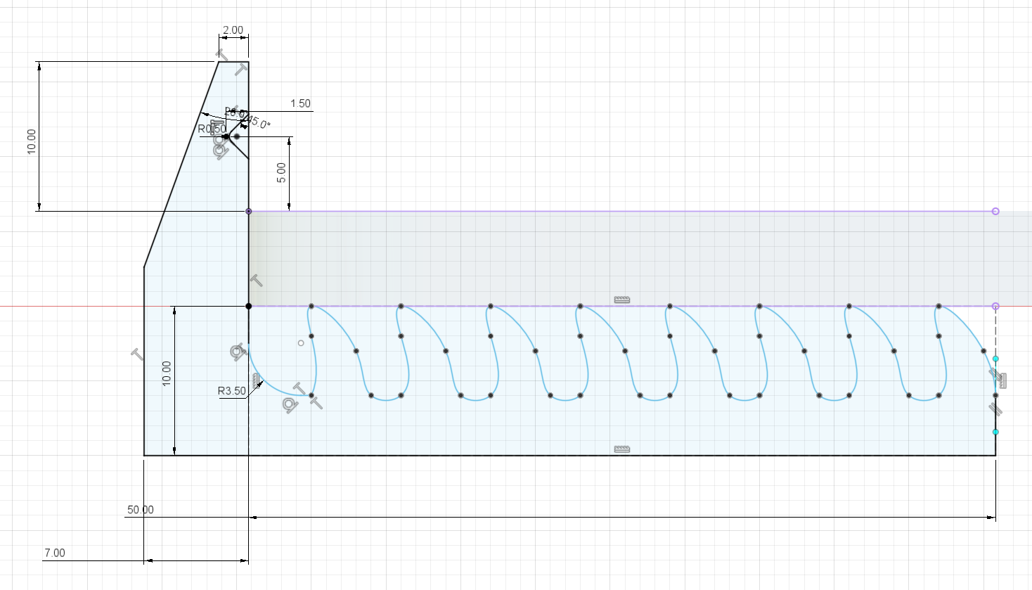
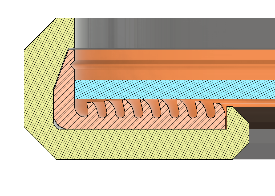
Moving on to the Rigid component:
It's going to be a lot more material than I had hoped, but I realized that if I'm going to have a continuous border of rigid material, I might as well make it possible for this to be used as a track system as well. So I wanted to provide surfaces, and sufficient reinforcement to those surfaces, to kinematically constrain in 5 DOF (allowing for movement along the direction of the extrusion of the above profile.) I should be able to then make fixtures that can attach to this rail, and if I want to lock 'axial' location, I can use a friction lock with the TPU. I don't want to lock against the silicone, because I'm worried that putting a significant shear load on the silicone could cause it to delaminate. Probably wouldn't be enough to cause any sort of catastrophic failure of the silicone, but I think it would make it get real ugly, real quick...this is probably my largest concern with the silicone layer on the glass....well, other than not making a giant, expensive mess. The great thing about silicone is that very little sticks to it. The shitty thing about silicone is that very little sticks to it.
The idea is that externally mounted items (what I'm referring to above) would use the two chamfers on the left side of the sketch, as well as the flat face that's perpendicular to the glass as the rigid contact planes ( could also use the flat plane on the left, I suppose). The chamfers on the right, under the glass, are for mounting any under-glass modules later. The flat plane on the bottom will primarily be used for the interface to the rest of the support structure.
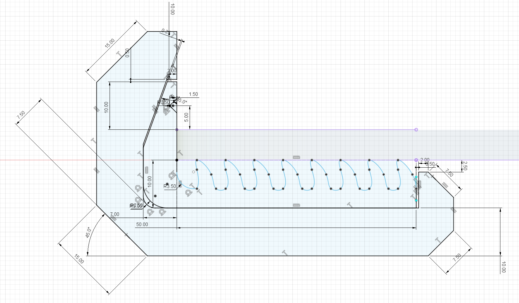
I went ahead and did a sweep of the above profiles around the perimeter of the glass:
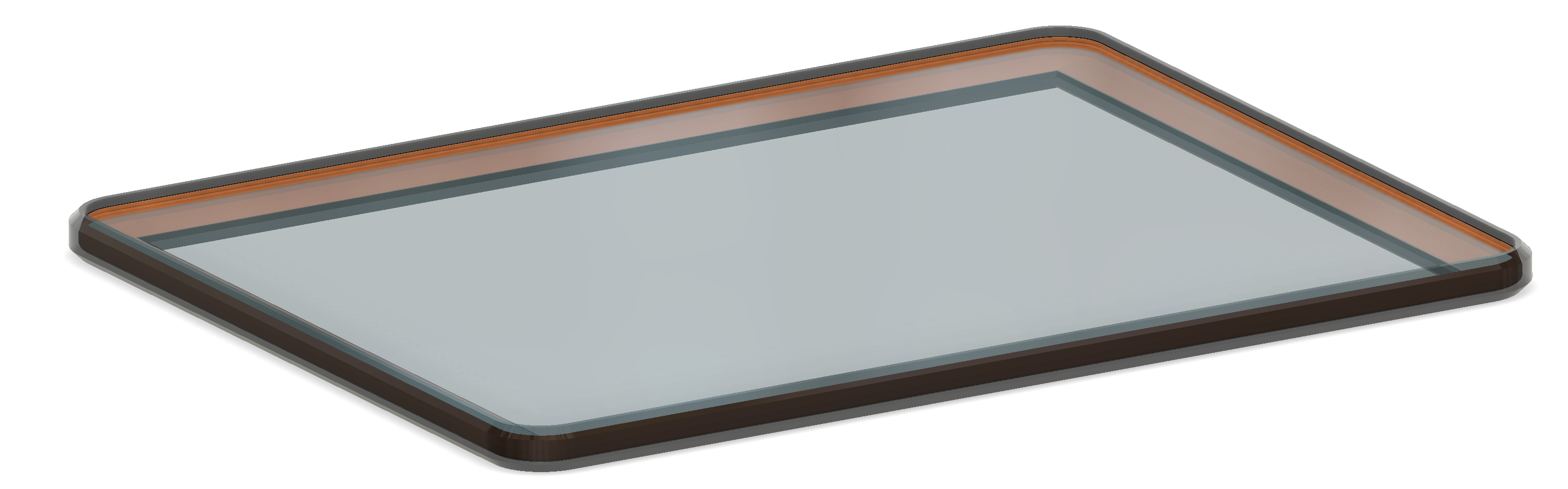
I am thinking I may actually go with resin for the borders, instead of PLA, which I'd been thinking previously. Not only would having the border in Smokey Black just look cool, it would also give me a pretty easy option to gap fill to get a nice, smooth outer face. That too would both help with coolness factor, as well as providing the funcitonal perk of nice, smooth travel if I put a little cart on the track.
I had previously decided against resin, because I didn't want it to poison the silicone (if you haven't run into this yourself, most UV resins have components that will poison platinum cure chemisty silicones unless you can get them COMPLETELY reacted or removed. It will leave you at best with an uncleanable, sticky surface. If there's a lot of free resin, the silicone won't cure at all.) But since I've revised the design to have the silicone only in contact with the seal, there shouldn't be any risk of contamination if the resin parts are reasonably well-cured and cleaned.
Here's a cross section prior to cutting in the arc in the seal:
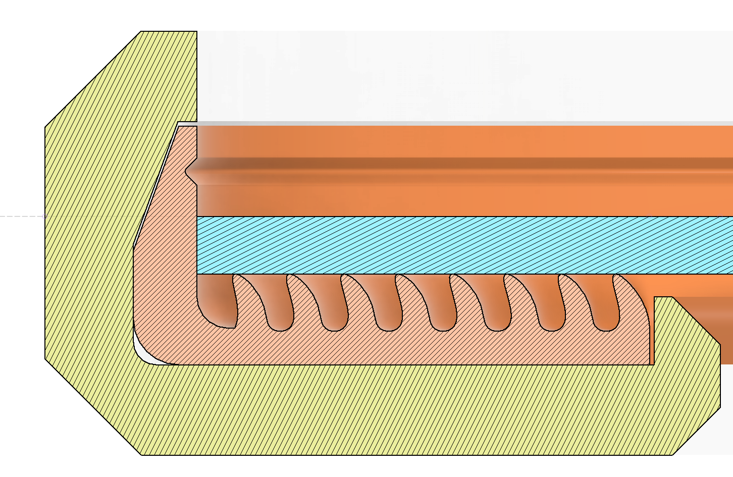
And here it is with the cut:
So now comes a part I've been dreading a bit (aka I have no clear idea yet what I'm gonna do). I need to break it up into sections, and figure out a good interface between the pieces to ensure a good seal.
For the Seal, I think I'm just going to go with 45 degree cuts at the interfaces and rely on the compression from the glass to bring them into intimate contact. To be safe, I may also gap-fill these seams in some way, but I'll decide once I've printed a couple of test pieces and got a feel for them,
For the Rigids, I'm thinking I'll have a support structure to the 2040 sub-frame come to each seam location and use these mount points to serve as both the support attach point and the connection between adjacent sections of the Rigid Border.
Based on a combo of the estimated total mass of the Seal parts, along with a quick slice of a couple of pieces to get a sense of the de-rating for less than full density, It looks like it's going to take a little under 1.5kg of TPU for the full seal. That's not awesome, but actually not quite as painful as I was starting to suspect.
I love how much faster this 0.8 nozzle is, but it's not doing much for my fears of not getting a defined contact line:
I'm going to print a couple of test pieces to see how the look and feel is...and play with the first Axial Flow parts that should be ready now :)
2024/02/12 - Starting on Support Structure(s)
The first Seal parts came out looking great, and feel really stable, seated on the glass. I only have two hesistations on pulling the trigger to start running all of em (there's a bunch, and it's TPU...it's gonna take a while).
The first is just the color. Seems small, but this isn't an insignificant cost of TPU, and also, once the silicone is poured, these are basically permanent. So whatever color I go with, I'm stuck with. I've printed the test parts in this Sainsmart neon blue TPU, which has printed better than any TPU I've tried to date (but I've also changed nozzles, heater blocks, and print profiles since my last batch of TPU printing, so grain of salt on that). I really like the color contrast of this bright blue with the SirayaTech smokey black resin. But given that one of the main uses of this table is to collect photos and videos of projects as they're worked on, I'm a little worried about the brightness and any other potentially undesirable side-effects that may come from having this neon blue in the lights and frame. I don't know enough about actual photography/videography to make an educated decision....so guess I'll just defer to pretty
The second is more important from a functional perspective, and that's the size. It has quite a bit more depth (extension under the glass from the edge) than I was envisioning. This doesn't present any problems from a structural standpoint, especially since the load isn't really evenly distributed anyway. But it does mean that I am potentially using up a lot more filament than necessary. This TPU is also quite stiff, so even using the single pad to lift up a corner of the table only induced a relatively small deformation in the fingies. So it might be wise to basically just shrink that whole 'shelf' to make the fingers thinner and closer packed, and reduce the total depth under the glass....but, then again....I have already printed two parts....fuck it, we'll do it live
So all that rambling leads to, "I'm going to start turning the crank on pumping out these Seal parts, and move on."
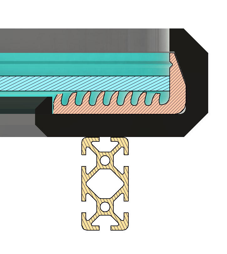
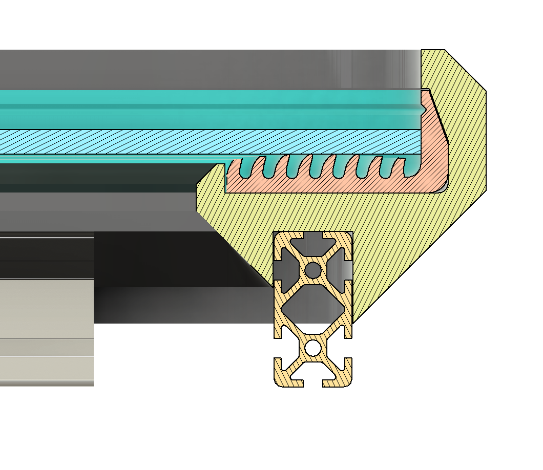
Taking a quick look at where I left off. Here's the cross section view of Glass Border parts, with the glass and the 2040 subframe. The latter is positioned correctly in XY, but I have flexibility in Z. I plan to adjust this Z offset based on what I decide to do for the support structure
Time to start getting the Rigid parts into final form. I'm going to start with splitting it up into discrete parts, like I did with the Seals. But for these I'm just going to go with vertical butt joints, instead of the 45 degree overlaps.
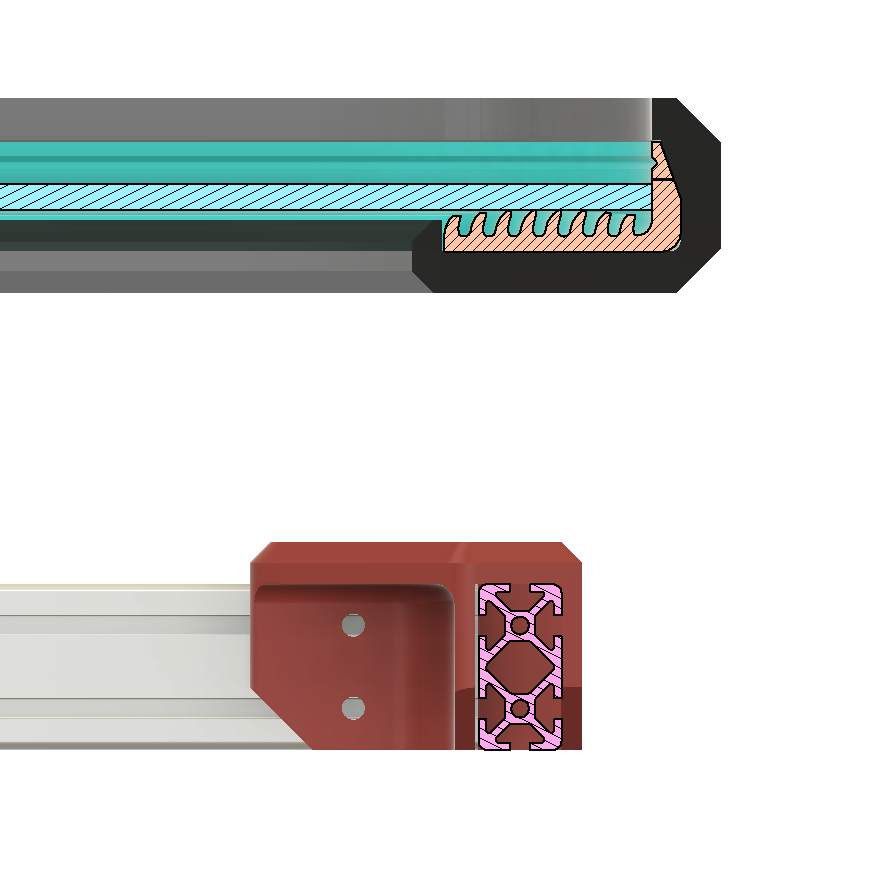
Actually, in looking at it more, I think I'm going to break up the existing 2040 frame, and instead directly mount the Rigid parts to the sections of 2040. Just to see how this would look, I just manually placed the 2040 section into place and removed the corner caps. Here's how the cross section looks now:
So I'm thinking I'd just basically put in a channel under the Rigid border pieces like this:
My only concern, from a structural side, is the region where it thins between the radius on the inside and chamfer on the outside. If the inward-facing flat up top is going to be the main load-bearing surface for something on the track that has a CG outside of the table area, this thin region will basically want to act like a hinge. I think I'm going to spend a few to revise this cross-section a bit to try to get a little better compromise of strength and materal usage.
2024/02/13 Bit of optimizing
Well, my fiddling with the cross-section to try to appease my fears over strength, now has me concerned about robustness :). So I decided it's worth putting in at least a little bit of time toward analysis to see if I can get a happy middle ground.
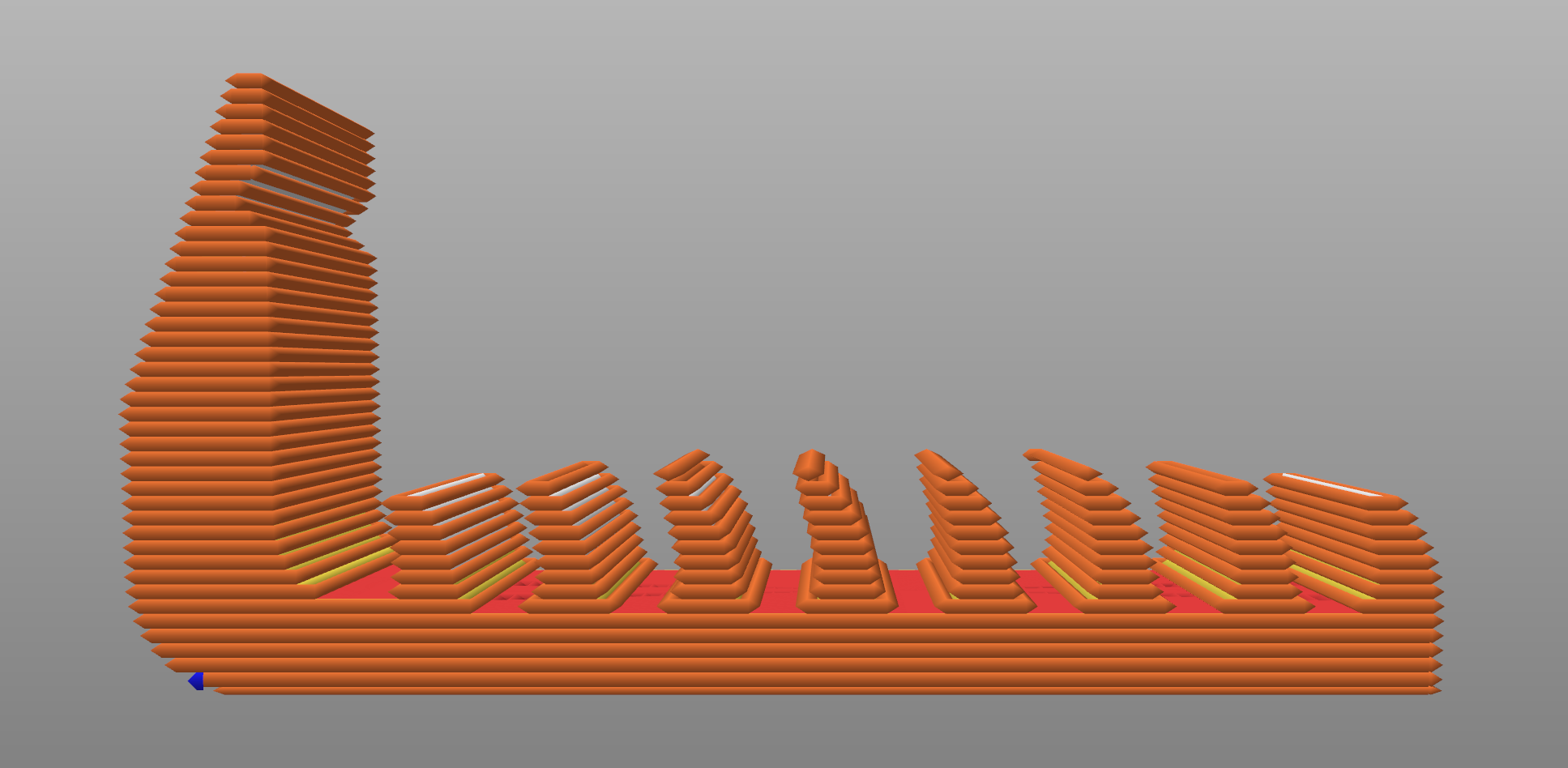
I'm not looking to go crazy, but since I currently have access to Fusion360's FEA tool. So I figured might as well use it!
The below has the faces that mate to the 2040 frame as fully fixed. I then applied a 100N force to the flat face (where the blue arrow is shown). This is roughly equivalent to a 10kg (22lb) gravity load.
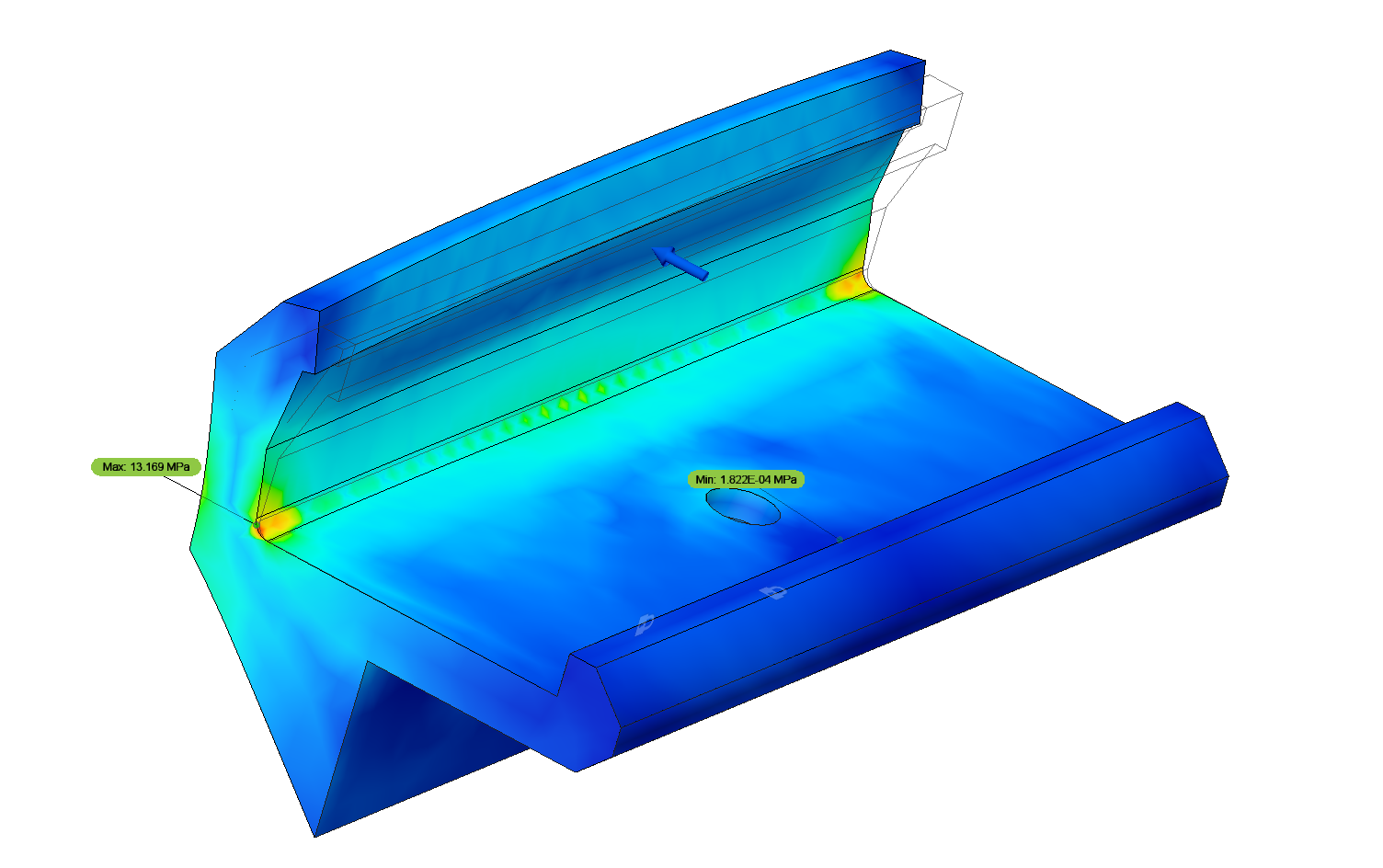
The sim gives a max stress of about 13MPa. The standard Siaraya Tech resisns that I usuaully use have a stated tensile strength of a little over 30MPa. This isn't the best possible news, in my opinion. Given that I'm sure my printed parts won't be perfect (in both geometry and in completeness of cure, I'd rather have a bit more head room than that.
The good news is that it looks like these stresses are only really at the stress risers in the corners. Since these seems don't need to seal, and won't be visible, I can toss some fillets on these and hopefully knock those down. Be back in a jif.