• Home
  • "BubsBuilds" Projects
      • Back
      • Assorted (hopefully) "Useful Stuff" Projects
      • Games
      • Generative Design Projects
      • Just Playin and Concept Demo Projects
          • Back
          • Print-in-Place
          • Flexure Fun
      • Pet Stuff
      • Printer Projects
      • Tool-related Projects
      • AgTech Projects
          • Back
          • Hydration and Hydroponics Projects
              • Back
              • Pumpin
              • Valvin
          • System-level Projects
              • Back
              • Project Fireplace
  • Tech Refs and Such
  • Books I Like

Latest Articles

  • Pepper Grow Station 2025 - Light Lifting System
  • Cam Valve - Gen3
  • Fractal Vise Jaws - Mechanical Bearings
  • High Flow Peristaltic Pump
  • Mech Tester

Most Popular

  • Displacement Sensor - Double Compound Flexure-based
  • 2020 Aluminum Extrusion stuff
  • Bolt-Sorting Sieve
  • Flexure Fractal Vise Jaws
  • Saturn Platen Removal Tool
  • Precision Dosing Pump
  • Mech Tester

BubsBuilds Projects

Generative Design Caliper Stand

Details
Parent Category: BubsBuilds Projects
Category: Generative Design Projects
Last Updated: 08 June 2023


Thanks to “Gabriel Fraga” on GrabCAD for the great caliper model!

Description: A little combo of Generative Design and Kinematic Constraint (how many cool words can ya stuff into a simple stand!?) It holds calipers. I designed two variations, one for my 6” Mitutoyos and one for my 8” Mituoyos….yeah, I’m sorta partial on my caliper brand ¯\(ツ)/¯ But, I have also used them with a handful of different brands and sizes, with results ranging from “meh, it’s fine” to “seems the same as the designed”. In my experience, the biggest factor that pushes it to the former mainly just comes down to the jaw geometry.

The 6 inch stand (shown above) and the 8 inch stand (shown below) were designed with the same basic approach to the Generative Design constraints described below.

The Design

This isn’t intended to be a ‘how to’ for using the Fusion360 Generative Design extension (nor is it me endorsing that particular product. I have used it for a handful of projects, but I can’t say that I think it’s cost-effective for the vast majority of people currently.) Instead, I just wanted to give a quick description of my thought process in the design of this little desk accent.

The below sketch (believe it or not, the product of a full grown adult, and not a small child) is meant to show the approximate Center of Gravity (the darker, down arrow in the center), along with my planned locations for the support points.

From here, it’s time to jump into Fusion360 and create some bodies at these support points and apply Load Cases. The below image shows the bodies that I created in the 6 in model. The two partial cylinders on the left make tangential contact against the jaws. The hemisphere contacts the back plane of the calipers, on the ground metal surface. The L-shaped contact on the right primarily provides a vertical support on the slide, but it also may provide some lateral support also (more on this below.) These bodies will be my “Preserve Geometries”. These are going to end up being a part of the final component.

This constraint scheme ain’t exactly exact, but hear me out…it’s fine :). What I probably should have done would have been to add an additional contact like the hemisphere, but just moved down slightly. That would have constrained that degree of potential rotation, as well as the translation along the vector path normal to the plane through the cylindrical force vectors….too much? Especially without additional supporting imagery?…Well, my hunch is no one is going to read this, let alone care THAT much about this level of detail on kinematic constraint, so I’m just gonna call this part here…

If you want to learn more about the concept of Exact Constraint, this book is my favorite on the topic. You can also learn more by just searching around on exact constraint, or also, commonly “kinematic constraint” or “kinematic design”…stuff like that. It will also usually get a chapter or so in most texts on Precision Engineering.

Now on to another vital part of the setup for the GD inputs, and that’s the “Obstacle Geometries”. You can think of these as “keep out zones” for the solver.

In the above you can see where I’ve added my ‘keep out’ zone for the calipers. I need to block out not only the space for the caliper in the final stand, but also any space that needs to be clear for getting them in and out of the stand, etc.

For this model, the Obstacles really are pretty straightforward. I essentially just added some margin around the calipers and then extended it out forward to ensure a clear path along that direction for inserting/removing the calipers from the stand.

Alright, we have our Preserve and Obstacle Geometries, and we have our Constraints and Loads applied. I can then run the simulation…it’s going to sit at “5%” for a shockingly long time…:)

And here are the results!

From here I just selected the outcome that I felt was most print-friendly and aesthetically pleasing, and that’s about that!

If you have any questions or comments, let me hear em! Thanks so much for checking it out! And if you’d like to see another of my generative design projects, you can take a look at my GD SD Card Tree.

Oh, and please note, I’m not saying this is THE way to design parts with Generative Design tools, this is just A way, and it’s a way that I enjoy :)

**Please note, many of the links contained in my articles are “Affiliate” links through that vendor. Unless specifically otherwise mentioned in the context of the link, these are items that I purchased and used from that same product page for whatever the project (or prospective project) was. I use these Affiliate links to help recoup a little of what I spend on project materials, etc. (if you’d like a sense of scale….in the week that I write this, I have brought in a startling $0.75 :) ).

No comments on “Generative Design Caliper Stand”

Generative Design SD Card (and Guitar pick, it turns out) Holder

Details
Parent Category: BubsBuilds Projects
Category: Generative Design Projects
Last Updated: 08 July 2023

I thought it might be kind of fun to make a Generative Design (GD) solution for holding SD/microSD cards…so that’s this :)

https://www.printables.com/model/459866-funky-sdmicrosd-card-tree

Setting up the Constraint Points

My favorite part about designing with GD tools is how beautifully it ties in with the principles of Exact Constraint/Kinematic Constraint, which have long been central to precision engineering applications (my ‘day job’ for most of the last ten years). It really creates a great opportunity to think about a design purely from a standpoint of constraints, loads, and keep out zones.

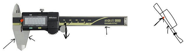
But anyway, aside from my fondness for playing around with these tools in general, back to playing around with them for an SD card holder specifically! The below sketch shows the rough concept for constraint points that I’m thinking for supporting the SD cards. And yes, I did put gravity pointing up…deal with it, orientation is a concept :) have you read Ender’s Game….if not, trust me, that isn’t THAT random of a connection…SOOO good!..what were we doin? Oh, yeah, SD card, got it. Yeah, 6 support points, 6DOF…checks out!

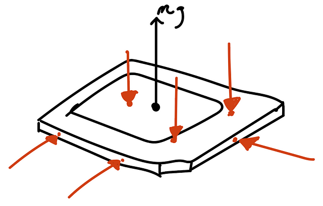
Because this is just for sitting on my desk, and I’m not intending to use this at all for transporting cards or the like, I’m actually not going to preload the cards into this constraint set (shocked gasps!) I’m ok with them jostling around a bit within their respective homes, so essentially what I’m going to do is just mirror that constraint set shown but with liberal clearances.

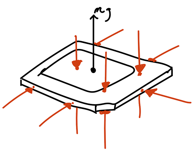
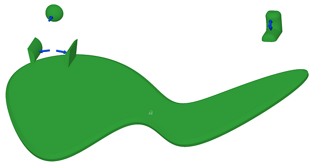
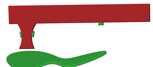
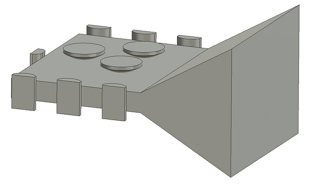
And here is the ‘one half’ constraint set implemented as solid bodies in Fusion360. One difference here is that I’ve added an additional constraint on the ‘side’ (the three column-lookin fellas there on the right). The further these side contacts can be spaced apart, the better the constraint against rotation around my lil mg vector shown above. So I wanted a constraint as close to the end of the card as is feasible, but my concern was that for some cards or some print conditions, this contact may not happen as intended, and so the redundant contact in the center was added.

And here is the full constraint set for a single card…you can mentally (or physically, have fun) draw your own force vector arrows :)

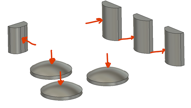
I then created a ‘keep out zone’ body. I just went with a simple block that fills the full tolerance/clearance zone for the SD card. I then put a simple flare out for access to grab the cards.

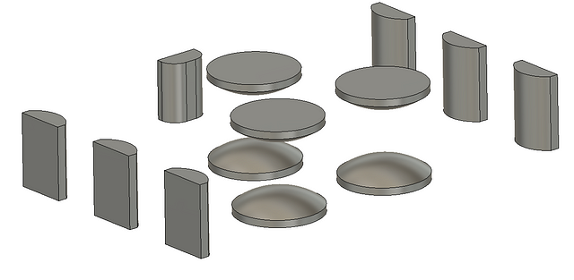
Alright! Off to the GD fun!…Oh, wait, a single SD card isn’t exactly ideal….so I did some patterning…from here on it’s a BIT of an eye sore…you’ve been warned…


Once all of the elements were populated, I moved to the fun of applying loads and constraints to this cluster…didn’t really think through the downsides of designing something with GD that is holding lots of discrete parts :)

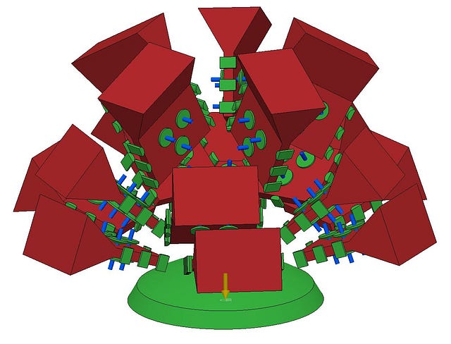
The only load case I applied was for a static loading, but I did significantly ‘overload’ it a bit. I applied a normal force to every one of the interface bodies shown above, and applied a 6DOF fixed constraint to the base.

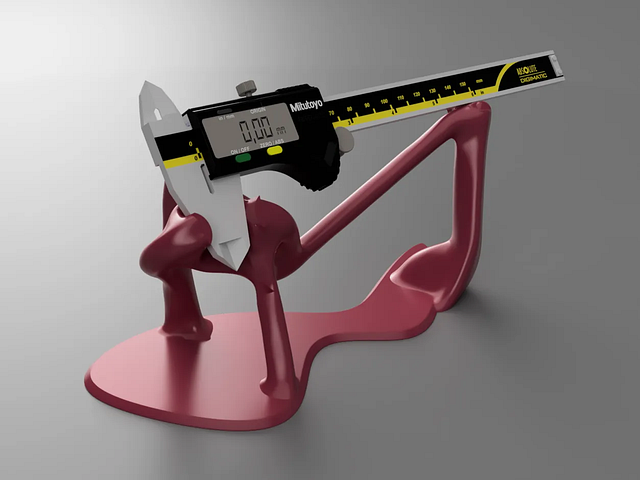
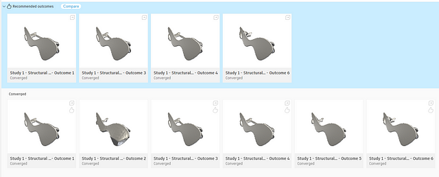
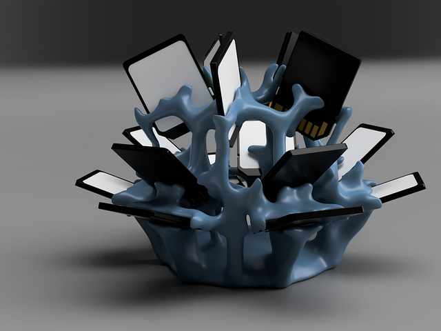
Unfortunately, it appears I ran another simulation on this file and can’t access the previous version….? 🥺 So I don’t have the full set of results from this run to show (and my license expired this week, twas fun while it lasted!), but here are the two versions that I saved and ultimately printed:

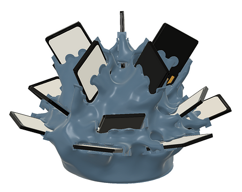
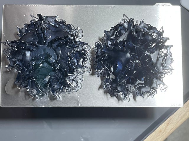
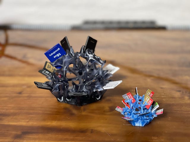
Here they are as amorphous blobs, fresh out the vat! They (roughly) line up with their respective modeled versions above. These were printed in Siraya Tech Fast — Smokey Black (pretty much my go to resin these days for ‘just works’ prints) on my Elegoo Saturn 8k (yes, I bought this AFTER the Saturn 2 came out…actually, I’ve bought two of them since the release of the 2. I personally just prefer the form factor and the capabilities seemed identical ¯\(ツ)/¯).

Oh, and quick aside, but if you print with resin and HAVEN’T already switched to flexible build plates…bruh….why??? :) Seriously though, Prusa, good on you for setting this standard, it is such a game changer to me!

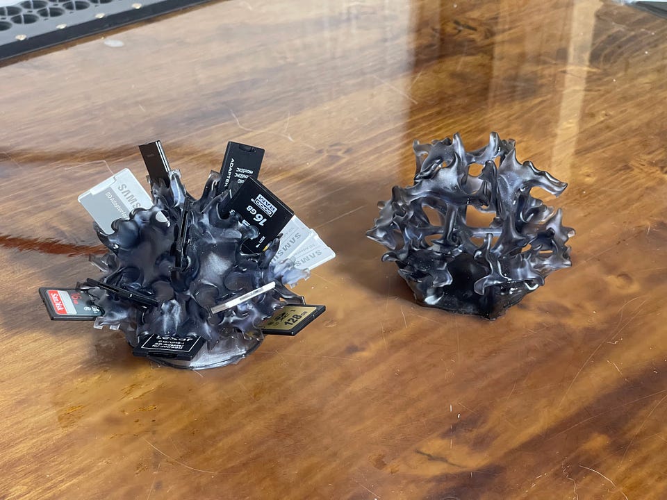
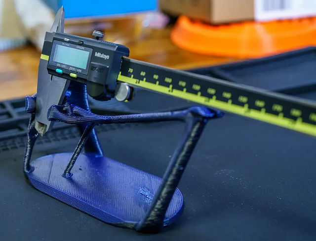
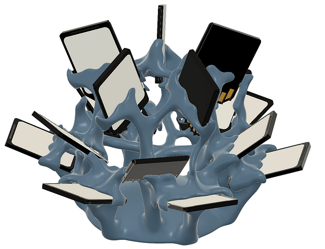
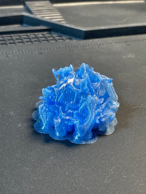
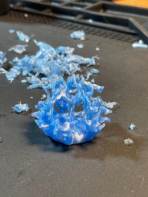
And here’s one scaled down to 46%, makin it a microSD card holder and printed on my Mk3s+ with a 0.25mm Revo nozzle on it. It’s printed in this PETG from a brand I hadn’t tried before. I bought three colors; the blue that the print is in, their transparent red, and the clear. They all have printed nicely, but the blue has hung around the longest and I’m pretty sure it’s taking up water pretty aggressively (and starting to get stringy)….hold on, what were we talkin about? Oh, right, the SD card holder…actually, I think that’s all I’ve got really on that :)


CAD models for the SD cards: Thanks for the nice card models!


Exact Constraint

If you’re interested in getting a quick handle on the concepts and examples in Exact Constraint, this book is the one I keep handy and always recommend to new folks in precision work.


Flexible Build Plates for resin printing

I have three resin printers, and I’ve put these on all three of them….come on Elegoo, can you please just do me a favor and toss these on at the factory??? They’re spring steel sheets, like what you’d find on a Prusa (since Mk2…I think?), but just clean stainless, sometimes with an etched or otherwise patterned surface.

I’ve used Wham bam (the regular, not the XTR versions), for all three of mine, but I’m very curious to hear comments from anyone that’s used the ‘generic’ versions these available at Amazon and the like.

The kits come with a magnetic plate that you adhere to your existing build plate surface. It’s USUALLY pretty straightforward (or at least it has been on the Saturn and Saturn 8k), but on one machine I did run into a problem where the addition of the magnetic plate caused the homing sensor to not be able to get within range. The fix was quick and easy, I just designed and printed a longer homing trigger. BUT if you don’t have a second printer handy, this could be a huge PIA! Once the magnetic plate is on, it’s not comin off easily! So I’d recommend doin a little googlin on your specific printer model just to see if there might be anything you’ll want to have printed prior, just in case.

No comments on “Generative Design SD Card (and Guitar pick, it turns out) Holder”

HydroHub - 4 in / 4 out distribution hub

Details
Parent Category: AgTech (aka finding a way to complicate and digitize gardening) Projects
Category: Hydration and Hydroponics Projects
Last Updated: 08 July 2023

This assembly brings together two Four Channel DrumCam Valve and an off-the-shelf peristaltic pump to provide distribution from 3 reservoirs to 4 'targets' (on the input side, I limited it to three reservoirs to leave one input as an air input to be able to clear lines. It doesn't have a very high flow rate, but it's more than enough for the tomato and pepper plants that it's currently feeding in my setup. 

The base of the assembly is the HydrationStationMount.stl printed part. It is secured to the t-slot aluminum extrusion with (up to) four, m5x10 BHCS fasteners (and some companion m5 t-nuts). 

The peristaltic pump attaches to the base with m3 heat set inserts and some m3 BHCS (or the head of your choosing).

The Four Channel DrumCam Valves attach to the base with four (2 each, only the bottom two sets of holes are used. It's plenty :) ) m5x16 BHCS fasteners fixed to the base with m5x9.5 heat set inserts.

One unfortunate design decision, realized too late, is that you can't access the fasteners for the attachment to the extrusion with the valves attached...sorry :/, but also...not a bit enough thing to feel like bothering to change it....so not THAT sorry I guess


No comments on “HydroHub - 4 in / 4 out distribution hub”
  1. High Flow Peristaltic Pump
  2. Precision Dosing Pump
  3. Stackable/Modular Peristaltic Pump Concept
  4. Initial/Manual Pump
  5. Cam Valve - Gen3
  6. Peristaltic Valve - gen1
  7. Four Channel DrumCam Valve
  8. Pepper Grow Station 2025 - Light Lifting System
  9. Planters
  10. Data Maker Electronics Enclosure

Subcategories

Assorted (hopefully) "Useful Stuff" Projects Article Count:  12

Like the bucket of assorted fasteners on that bottom shelf, this category is for stuff that I didn't know how to group...oh, and speaking of those fasteners, check out the little sortin fella!

2020 Aluminum Extrusion Hardware

Quick Bolt Sorter

General Purpose Turntable - Gen1

Games Article Count:  1

Generative Design Projects Article Count:  3

During the good financial decision-making times of Covid lockdowns, etc. I decided it was a good idea to buy a license for the Fusion360 Generative Design extension...Good news, I did finally pay that off :) I had worked around, and been somewhat involved in a handful of Topology Optimization/Generative Design projects through my work, and I've found the tech super interesting for some time. So after the free trial, and feeling like I was just starting to gain some level of competence in Fusion360's tool....I done did it, and bought the year. Ok, now that I'm done justifying that to myself...I mean you...

<engineering/design> What I really like about Generative Design is that it forces the designer to think about the thing they are trying to design from it's core requirements: Forces, Interfaces, and Keep Outs. I think it's far from perfect, especially given the still very primitive Design For Manufacture capabilities these tools have (among other shortcomings, but this one is certainly a big one to me.)

<precision engineering> One last also (for now), but ALSO, what I find exciting about these tools from a precision engineering perspective, is that the above-mentioned focus on forces and interfaces, these tools are extremely well-suited to kinematic/exact constraint designs! I think every one of the Generative Design projects below features at least some aspects of kinematic constraint (I say, "I think" because I may or may not be writing this before I go through my files and remind myself what all I actually made vs what I just thought about making ¯\_(ツ)_/¯ )

Generative Design Projects


JFS Projects Article Count:  14

AgTech (aka finding a way to complicate and digitize gardening) Projects Article Count:  12

Hydration and Hydroponics Projects Article Count:  8

Peristaltic Pumpin Article Count:  4

A lot of projects I work on/have worked on seem to involve the controlled movement of fluids. Below is a bit of a history of my builds involving attempts at obtaining this controlled movement for incompressible fluids. I haven’t done much myself with making custom solutions for the compressible stuff, but if you’re interested in such things, I thoroughly enjoy Major Hardware’s “Fan Showdown” series :)

This article/section is by no means intended as a thorough overview on the design and operation of pumps. While I will try to give some overview on operating principles and design considerations as I go, this is mainly just going to be a wander through my personal builds and experiences.

Peristaltic Pumps

What is a peristaltic pump?

I’m sure there are innumerable sources online for (much better) detailed discussions of the workings of peristaltic pumps. So I’m just going to hit the highlights, and I’ll try to remember to find some promising links and add them below, should a deep dive seem intriguing to ya.

Basic Operation:

The fluid being pumped is carried into the pump in a compliant tubing. This tube is routed around some portion of a circular/cylindrical path around the axis of the pump and then exits the pump. This is one interesting/attractive aspect of peristaltic pumps, the fluid never has to leave the tube that it is in, making these pumps well-suited to situations where contamination and/or leaks are highly undesirable. The housing that features the cylindrical wall that the tubing is being routed along can be considered the Stator, and that is generally the nomenclature that I tend to use.

So if there’s a Stator, there must be a Rotor…? Yup, the rotor includes some set of features that extend out to some defined gap between this feature and the Stator wall. These features, which in many peristaltic pumps are rolling element bearings, pinch the tubing to the point of sealing (ideally) the tube. As the rotor turns, this contact point proceeds around the circumference. Because the pinched point of the tube is sealed, the volume of fluid in the tube ‘ahead’ of the pinch point are, as a result, pushed forward. So, keep rotating, keep pushing….pretty much as simple as that!

Pros:

  • Positive Displacement Pump
    • Because the pinch point is (ideally) fully sealing the tubing, the amount of fluid moved is directly proportional to the movement of the pump. This makes them very good choices for things like dosing pumps or other applications where the desired volume of fluid to be moved needs to be deterministic.
    • This is a large driver for my initial interest in using peristaltic pumps. Their deterministic flow is/was very attractive for my plant growth experiments. They can give very repeatable watering volumes and nutrient concentrations.
  • Fluid Isolation
    • Because the fluid never leaves the tubing, these pumps can be suitable for moving hazardous materials. For example, I have been using a peristaltic pump for transferring 99% IPA
  • Relatively Simple Construction
    • Because the fluid does not have to be sealed within the pump, these pumps lend themselves well to DIY builds. No shaft seals, gaskets, etc. or complex (at least to do well) impeller design needed.
  • Self-priming and Head height
    • If well-sealed, these pumps are capable of self-priming (and even pumping air) and of achieving pretty impressive head heights (the measure of how high above the pump it can pump a column of water)

Cons:

  • High drive torque
    • Because of the preloading needed against the tubing, and the rolling friction, even with good rolling elements (more below on this), it can be quite easy to end up with designs that require quite a lot of drive toque.
  • Tubing wear
    • With the relatively large deformation and high number of cycles, the tubing will eventually fail, either due to material wear, fatigue cracking, or who knows what else. Because this failure mode can cause fluids leaking into your pump not designed to experience this fluid, this failure can potentially be quite problematic. So the use of high-quality tubing material and a plan for periodic maintenance, are worthwhile.

Test Build 1

A couple of years back, I had a concept for an in-line-mixing hydroponics system. The idea being that the supplies to the system would be just pure water and nutrient concentrates, and a series of pumps and valves would allow precise dosing mixes to each target plant in a system (I refer to this concept as Rail Yard Hydro, since it moves the fluids around the tubing network quite like rail cars are moved around a rail system. I’m planning to add a separate page diving into that one a bit deeper since it is the design scheme I am using in my current projects.)

Well, to facilitate this plan, I wanted to find an option for a dosing pump that I could integrate in to my control system (aka Arduinos and Raspberry Pi’s :)). Unfortunately, I quickly found that a servo-driven peristaltic pump could easily set me back north of $100….so I set out to spend many multiples of that making my own!

Actually, when I saw the pricing, I decided I should see if I could make myself a cheapo, manual version that I could use to just test out some basic questions on the Rail Hydro idea (mainly verifying that I could induce good material mixing in-line and that there was no cross-contamination between fluid reservoirs.) And so, ‘twas this endeavor that resulted in the pump I’m apparently referring to as “Test Build 1”

Design Objectives:

  • Be a peristaltic pump
  • Provide a full seal (at 100mm head)
  • Be hand-cranked
  • Not require any parts that would have to be ordered (I’m impatient)

The Build

She ain't pretty (especially after a good while of getting knocked around), but the pic above shows the dual pump setup I rigged up for my testing needs. I was VERY pleasantly surprised that, other than a tweak to the hand wheel, these things worked pretty damn well!

I decided upfront that I was going to go with a resin printed build, because I thought the high stiffness and good surface finish throughout the 'pinch region' would give me a better chance. Since I was already going to have the good surface roughness, I might as well also integrate the main bearing into the printed parts.

In the image of the model, below, the Stator is the part shown in green, and the Rotor is shown in blue(ish.) Riding on the rotor are roller skate bearings to provide the contact with the tube. Race 1 has v-grooves on both sides of the race, providing the main constraint for locating the rotor, and Race 2 has a v-groove on the Stator, but only a single plane of contact on the Rotor side. This keeps from over-constraining the bearing.

The absurdly overkill bolt running through the center is a real showcase of "using what I had on hand" :) in that these were the only bolt/nut sets I had on hand with the length I was looking for.

Valving Article Count:  3

System-level Projects Article Count:  4

Project Fireplace Article Count:  4

Just Playin and Concept Demo Projects Article Count:  8

Print-in-Place Designs Article Count:  1

Flexure Fun Article Count:  5

Pet Stuff Article Count:  1

Printer Stuff Article Count:  3

Tool-related Projects Article Count:  6

WIP Article Count:  3

A temporary home for projects I'm currently working on.

Page 6 of 16

  • 1
  • 2
  • 3
  • 4
  • 5
  • 6
  • 7
  • 8
  • 9
  • 10

Login

  • Forgot your password?
  • Forgot your username?
  • Create an account

Please note, many of the links contained in my articles are “Affiliate” links through that vendor. Unless specifically otherwise mentioned in the context of the link, these are items that I purchased and used from that same product page for whatever the project (or prospective project) was. I use these Affiliate links to help recoup a little of what I spend on project materials, etc. (if you’d like a sense of scale….in the week that I write this, I have brought in a startling $0.75 :) ).

TERMS OF SERVICE

  • Policies
Copyright © 2022 - 2025 JFS Agri, LLC