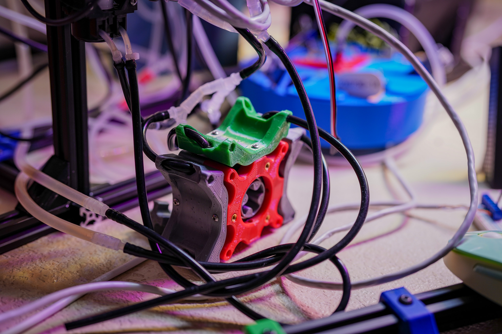
In my seemingly-endless tinkering with Peristaltic pumps, it occurred to me that the same concept used in a peristaltic pump to move fluid, could also be used to create a valve mechanism. So I decided to give it a shot, and it actually works pretty well!
Design
 |
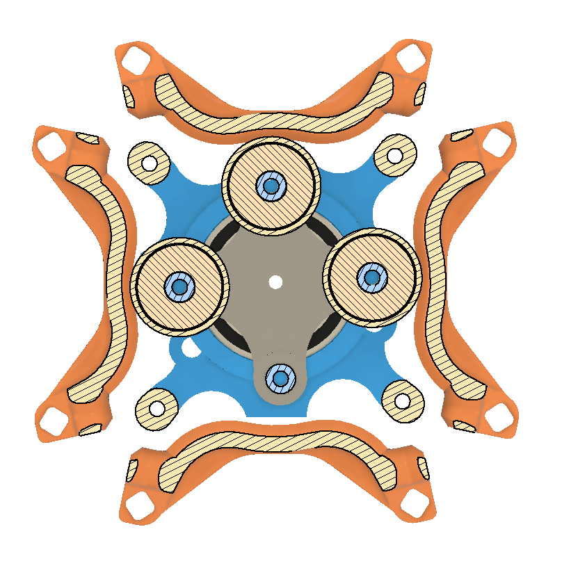 |
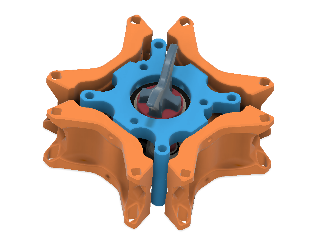
There are three main elements to the design:
- The Shoes - These are shown in orange in the above images. These parts include the guides for the tubing, and the wall that the tube will be compressed against when closed. There is one shoe for each tube/channel that is being valved.
- The Stator(s) - Shown in electric blue in the images. These two parts bolt together, clamshell style, and act as the frame. They also house the main bearing journals that support the rotor.
- The Rotor(s) - Red and grey in the images. Both ends of the rotor have a motor coupler bearing journal. The rotors also have the attachment points for the bearings that will compress the tubing.
BOM
- Printed Parts
- (Qty 2) Frame.stl - These make the Stator
- (Qty 1) Rotor_Upper.stl
- (Qty 1) Rotor_Lower.stl
- (Qty 4) Shoe.stl
- (Qty 3) BearingCap.stl - These extend the contact patch for the bearing to cover the full tube and also can be easily swapped to vary the compression gap for different tubing and/or seal.
- (Qty 1) HandCrank.stl - To manually operate the valve - There are also mount locations on the Frame parts to attach a servo, but currently the drive torque required seems prohibitive (in my opinion)
- COTS
- (Qty 2) 6806-2RS Bearings / 30x42x7 - The 'main bearings'
- (Qty 3) 608-2RS Bearings / 8x22x7 - Aka roller skate bearings. These are the compressors (or so I will now call them)
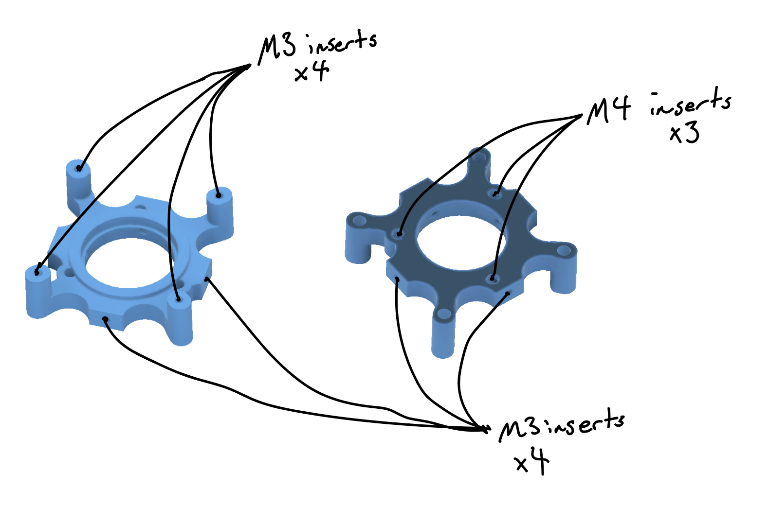
- (Qty 16) M3 Heat Set Inserts - Numerous spots, see below images.
- (Qty 6 - Optional) - M4 Heat set inserts - These are for the top and bottom mount locations intended for motor mounts.
Heat set locations
One of the frames will have four, M3 heat sets inserted for attaching the frames together. These should be inserted from the inside (the smaller diameter).
Both frames will get four, M3 heat sets inserted around the perimeter, for attaching the shoes.
If you are going to insert the M4s into the frames, be careful when inserting the M3s to not obstruct the one M4 hole that intersects. You may want to use a shorter M3 for these holes.
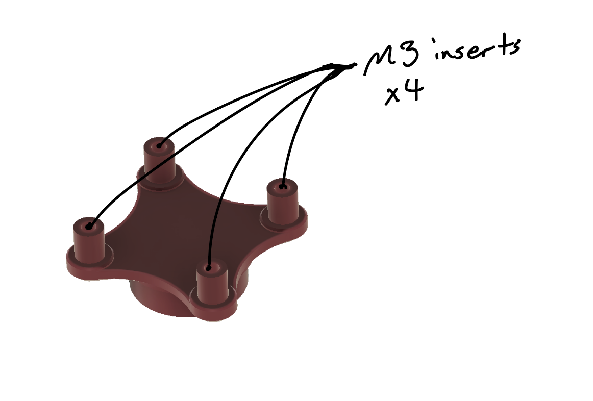
The final M3s go into the Rotor_Upper. I was wanting to test using the expansion of the post when inserting the heat set to make an interference fit with the bearing, but I was too conservative on my post diameter. So no need to have the bearings in place when inserting the heat sets.
 |
 |