JFS Projects
- Details
- Parent Category: Hydration and Hydroponics Projects
- Category: Valving
In my seemingly-endless tinkering with Peristaltic pumps, it occurred to me that the same concept used in a peristaltic pump to move fluid, could also be used to create a valve mechanism. So I decided to give it a shot, and it actually works pretty well!
Design
 |
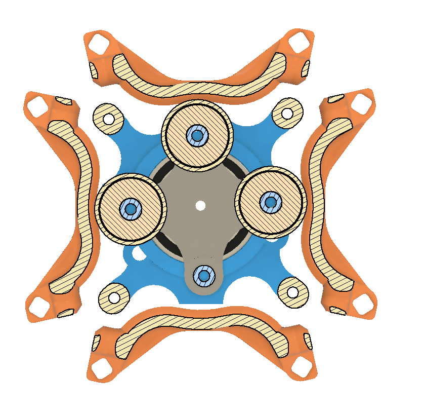 |
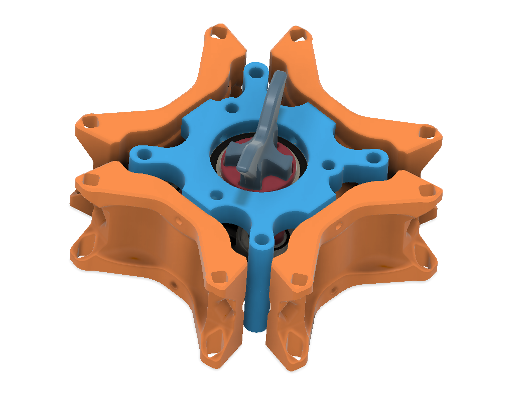
There are three main elements to the design:
- The Shoes - These are shown in orange in the above images. These parts include the guides for the tubing, and the wall that the tube will be compressed against when closed. There is one shoe for each tube/channel that is being valved.
- The Stator(s) - Shown in electric blue in the images. These two parts bolt together, clamshell style, and act as the frame. They also house the main bearing journals that support the rotor.
- The Rotor(s) - Red and grey in the images. Both ends of the rotor have a motor coupler bearing journal. The rotors also have the attachment points for the bearings that will compress the tubing.
BOM
- Printed Parts
- (Qty 2) Frame.stl - These make the Stator
- (Qty 1) Rotor_Upper.stl
- (Qty 1) Rotor_Lower.stl
- (Qty 4) Shoe.stl
- (Qty 3) BearingCap.stl - These extend the contact patch for the bearing to cover the full tube and also can be easily swapped to vary the compression gap for different tubing and/or seal.
- (Qty 1) HandCrank.stl - To manually operate the valve - There are also mount locations on the Frame parts to attach a servo, but currently the drive torque required seems prohibitive (in my opinion)
- COTS
- (Qty 2) 6806-2RS Bearings / 30x42x7 - The 'main bearings'
- (Qty 3) 608-2RS Bearings / 8x22x7 - Aka roller skate bearings. These are the compressors (or so I will now call them)
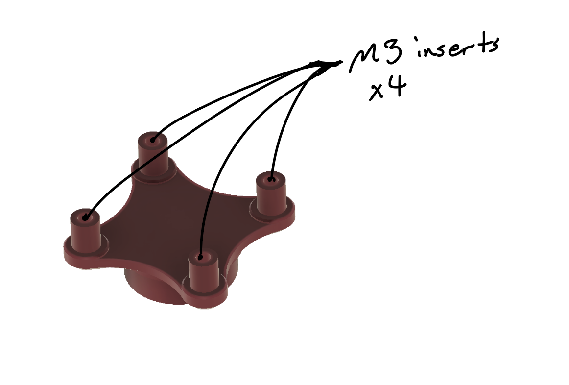
- (Qty 16) M3 Heat Set Inserts - Numerous spots, see below images.
- (Qty 6 - Optional) - M4 Heat set inserts - These are for the top and bottom mount locations intended for motor mounts.
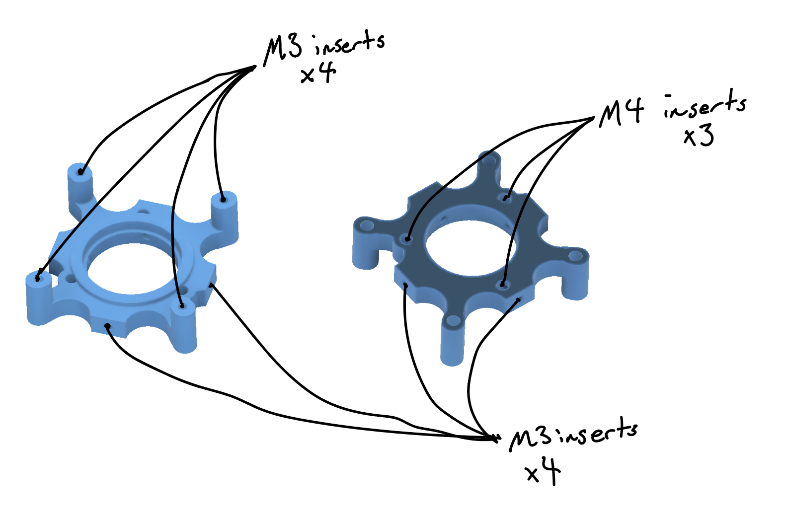
Heat set locations
One of the frames will have four, M3 heat sets inserted for attaching the frames together. These should be inserted from the inside (the smaller diameter).
Both frames will get four, M3 heat sets inserted around the perimeter, for attaching the shoes.
If you are going to insert the M4s into the frames, be careful when inserting the M3s to not obstruct the one M4 hole that intersects. You may want to use a shorter M3 for these holes.
The final M3s go into the Rotor_Upper. I was wanting to test using the expansion of the post when inserting the heat set to make an interference fit with the bearing, but I was too conservative on my post diameter. So no need to have the bearings in place when inserting the heat sets.
 |
 |
- Details
- Parent Category: Hydration and Hydroponics Projects
- Category: Valving

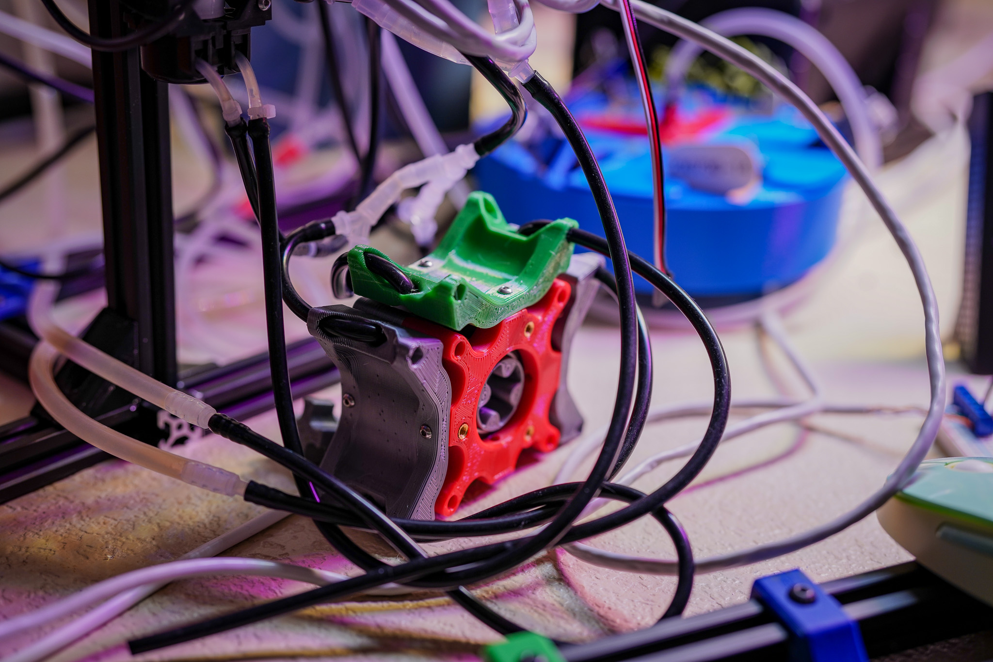
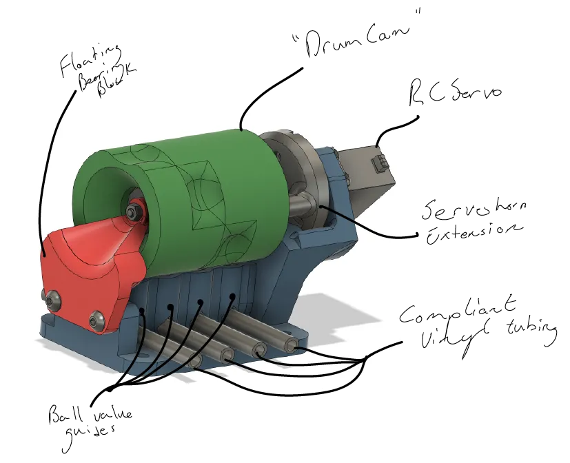
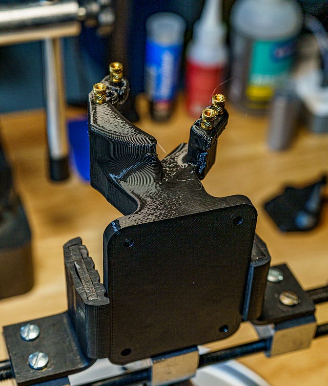
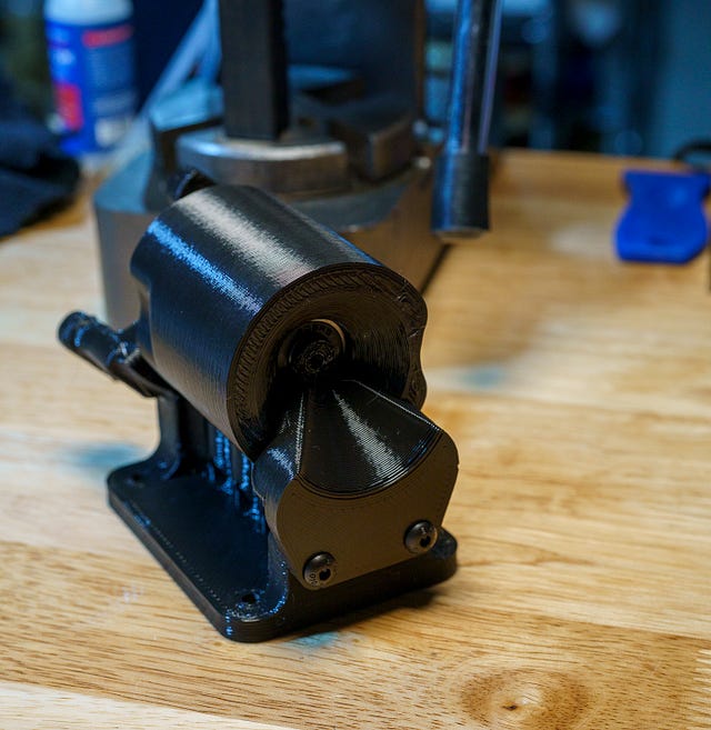
This design is for a digitally-controlled, four ‘channel’ valve assembly. I designed this specifically for the application shown in the picture above, where I wanted to be able to controllably dose from individual reservoirs to individual target plants. By combining a couple of these valves with a peristaltic pump, I could supply four plants from up to three reservoirs.
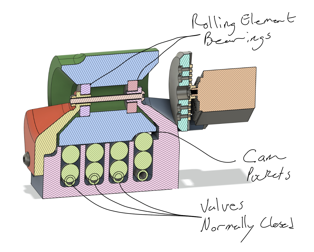
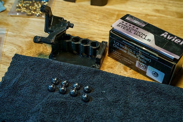
The valve works by the camshaft pushing steel balls against the tubing passing through the valve. The channels are closed except when the cam rotates such that the ‘pocket’ for that channel is rotated such that the ball can lift and release the tube. The video below shows one in action.
Design Overview
A good friend (and far better engineer than I) was kind enough to record a full Design Review video for this…but technical difficulties (aka I’m still new to OBS Studio) meant none of his audio was captured…oops…I am curious if people would actually be interested in these sorts of Design Review videos, any opinions or suggestions would be much appreciated!
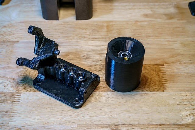
Parts List
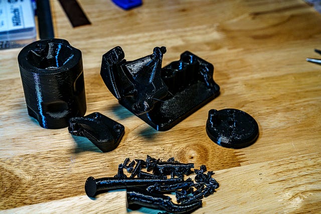
Printed Parts:
I’ve now made a handful of these valves, and I’ve made all of them from Overture PETG. I generally like working with PETG, and it holds up well for these. The only downside is that PETG does wear a bit at the contact between the drum and the steel balls. I haven’t experienced any problems, but I anticipate it will lead to progressively worse sealing over time. I didn’t want to use PLA because I expect mine to see a fair bit of UV exposure, but I’d be quite curious to hear what else folks try and what works well.
- DrumCam.stl
- Housing.stl
- CamSupport.stl
- ServoInterface.stl

Please note, I sliced/printed these prior to the release of organic supports in Prusa Slicer, of which I am a very big fan. If I were printing these today I would use organic supports…and actually, I just realized that for the build I did in the images below, I did indeed slice it with them. But the screenshot I saved, is the screenshot I saved!
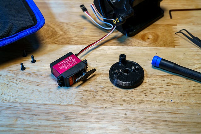
COTS parts
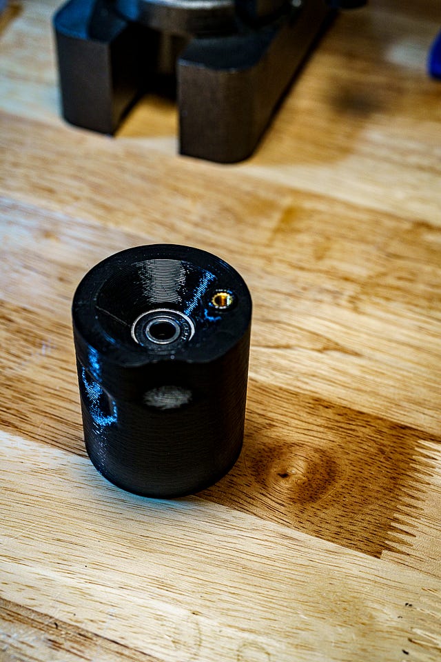
- (Qty 2) 608 2RS Bearings — Aka skate board bearings. There’s not much demand on these bearings unless you’re putting yours in some weird/harsh environment, so any 8x22x7mm bearing should do fine.
- (Qty 1) DS3225 Servo — It was originally designed for, and still can be built with, an MG995 servo, but while it seemed to operate fine for several weeks, I felt like it sounded like it was loading closer to stall than I wanted.
- (Qty 8) 1/2" or 12.5mm balls — I have just been buying these in different sizes recently, but you obviously don’t need 100 pieces for this project.
- (Qty ?) 5mm x 8mm Silicone Tubing — You’re looking for a compliant/soft tubing with the matching ID/OD. You would probably be fine (and maybe even get slightly better sealing) with a thicker wall, but at the cost of more Cam wear.
- (Qty 4) M4 x 8.1 Heat set inserts — You should be able to use any length of M4 insert, just make sure to choose the corresponding fastener accordingly.
- (Qty 1) M5 x 9.5 Heat set insert — This will be the load path from the servo to the camshaft, so just make sure you have enough thread engagement, but with it being M5, really any depth of insert should be fine.
- There are a number of options for fasteners, and I tend to just use assorted kits for each size, which is overkill for the few fasteners you’ll need for this. So I’ll list them here
- (Qty 4) m4 x 10 BHCS
- (Qty 1) m5 x 30 BHCS — could also sub this with an m4x30 and replace one of the m5 nuts with an m4 nut, but may want to also toss in a washer just to be safe.
- (Qty 2) m5 x 18 BHCS
- (Qty 3) m5 hex nuts
Assembly


This project is part of a collection of AgTech projects that I am working on putting together as an open source hardware project, JFS Agri. I am excited by the intersection of growing my own food and playing with tech toys :) if you’d like to see a summary of the projects along the way, I’ve started an overview page here. I’d love to find like-minded folks with a similar interest that are interested in collaborating, generating data, or just chatting about AgTech!
- Details
- Parent Category: System-level Projects
- Category: Project Fireplace
Continuing work on the Project Fireplace pepper growing system (aka, the instrumented produce-growing system(s) that will live above the fireplace). I decided the next subsystem to tackle for this build is the frame and structure for the lighting.
The main challenge for this subsystem is the need to be able to raise and lower the lighting components relative to the plant. This is important for both reducing the wasted light, but also for maintaining lighting intensity when plants are in early growth stages.
To be fair, I could kick the can on this problem, and instead try to accomplish this by moving the hydro system to move the plant instead....but as much as I love an opportunity to procastinate, that sounds like a real pain in the ass. So light moving it is.
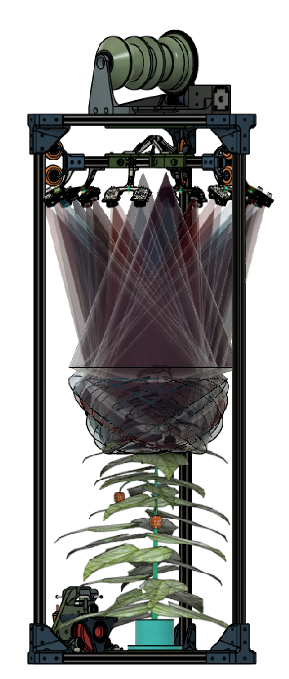
Design Overview
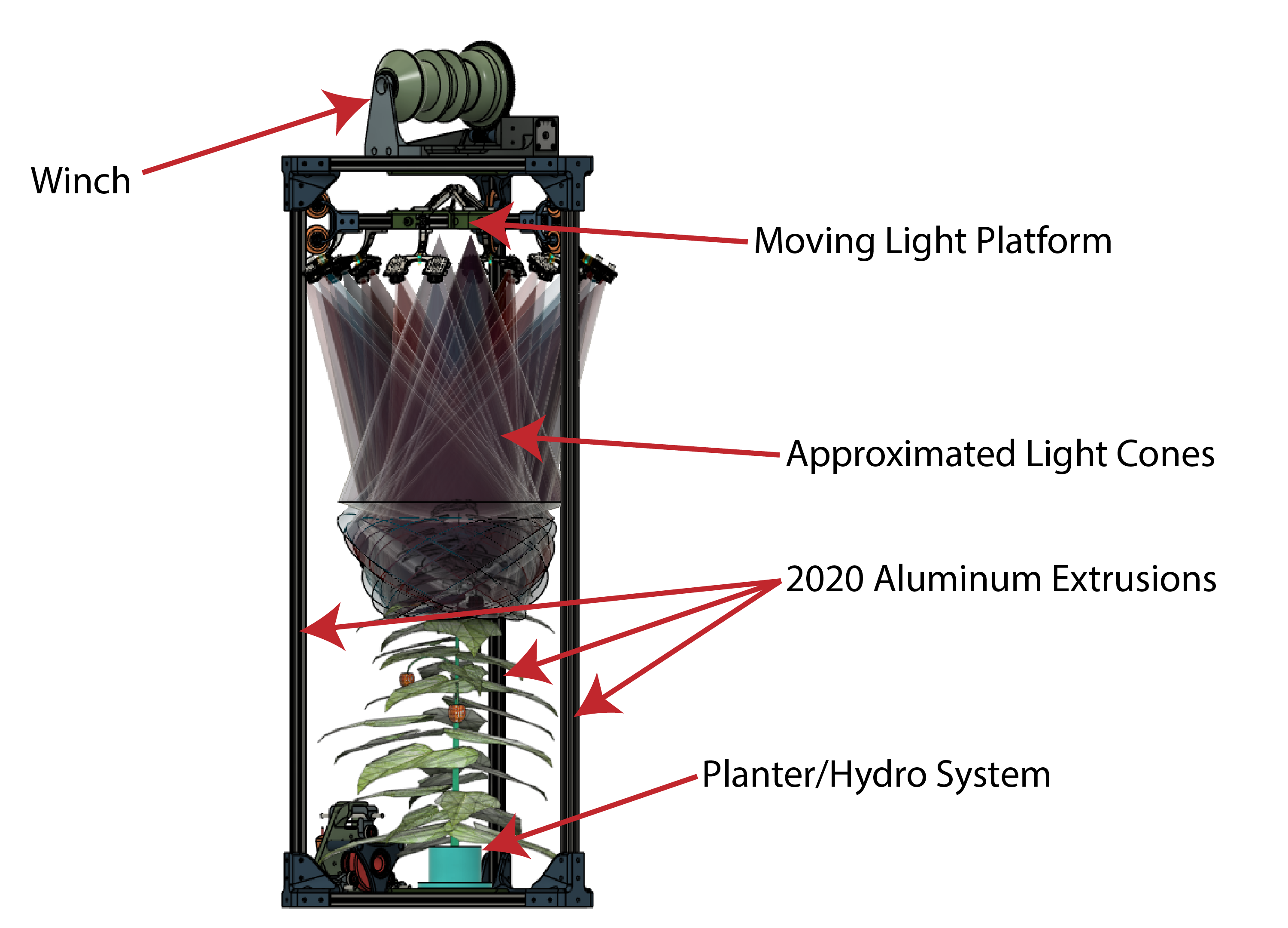
The main structure of the system will be provided by some 2020 aluminum extrusions connected by 3d printed (FDM from PETG) brackets. On top of that structure sits an admittedly oversized winch. The winch raises and lowers the moving platform that the LED clusters will be attached to.
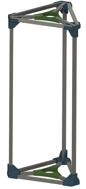
Taking a closer look at each of those, let's start with the base and top frame assemblies. Both are the same construction, shown in the image from the model shown below.
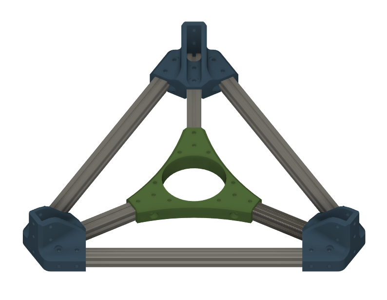
It is made up of 6 pieces of 2020, connected together with four PETG brackets. The brackets in the center provide structure and attach points for 1) the planter/hydro system on the bottom and 2) the lift system on the top. The top and bottom assemblies are connected together with a set of vertical 2020 extrusions. The length of these extrusions sets the total height of the system. I went with 1m lengths.
WORK IN PROGRESS - This article is a work in progress. If there are specific aspects of the project you're eager to know more about, feel free to drop a comment here or on my socials and I'll prioritize getting that part added!
Subcategories
AgTech (aka finding a way to complicate and digitize gardening) Projects Article Count: 12
Hydration and Hydroponics Projects Article Count: 8
Peristaltic Pumpin Article Count: 4
A lot of projects I work on/have worked on seem to involve the controlled movement of fluids. Below is a bit of a history of my builds involving attempts at obtaining this controlled movement for incompressible fluids. I haven’t done much myself with making custom solutions for the compressible stuff, but if you’re interested in such things, I thoroughly enjoy Major Hardware’s “Fan Showdown” series :)
This article/section is by no means intended as a thorough overview on the design and operation of pumps. While I will try to give some overview on operating principles and design considerations as I go, this is mainly just going to be a wander through my personal builds and experiences.
Peristaltic Pumps
What is a peristaltic pump?
I’m sure there are innumerable sources online for (much better) detailed discussions of the workings of peristaltic pumps. So I’m just going to hit the highlights, and I’ll try to remember to find some promising links and add them below, should a deep dive seem intriguing to ya.
Basic Operation:
The fluid being pumped is carried into the pump in a compliant tubing. This tube is routed around some portion of a circular/cylindrical path around the axis of the pump and then exits the pump. This is one interesting/attractive aspect of peristaltic pumps, the fluid never has to leave the tube that it is in, making these pumps well-suited to situations where contamination and/or leaks are highly undesirable. The housing that features the cylindrical wall that the tubing is being routed along can be considered the Stator, and that is generally the nomenclature that I tend to use.

So if there’s a Stator, there must be a Rotor…? Yup, the rotor includes some set of features that extend out to some defined gap between this feature and the Stator wall. These features, which in many peristaltic pumps are rolling element bearings, pinch the tubing to the point of sealing (ideally) the tube. As the rotor turns, this contact point proceeds around the circumference. Because the pinched point of the tube is sealed, the volume of fluid in the tube ‘ahead’ of the pinch point are, as a result, pushed forward. So, keep rotating, keep pushing….pretty much as simple as that!
Pros:
- Positive Displacement Pump
- Because the pinch point is (ideally) fully sealing the tubing, the amount of fluid moved is directly proportional to the movement of the pump. This makes them very good choices for things like dosing pumps or other applications where the desired volume of fluid to be moved needs to be deterministic.
- This is a large driver for my initial interest in using peristaltic pumps. Their deterministic flow is/was very attractive for my plant growth experiments. They can give very repeatable watering volumes and nutrient concentrations.
- Fluid Isolation
- Because the fluid never leaves the tubing, these pumps can be suitable for moving hazardous materials. For example, I have been using a peristaltic pump for transferring 99% IPA
- Relatively Simple Construction
- Because the fluid does not have to be sealed within the pump, these pumps lend themselves well to DIY builds. No shaft seals, gaskets, etc. or complex (at least to do well) impeller design needed.
- Self-priming and Head height
- If well-sealed, these pumps are capable of self-priming (and even pumping air) and of achieving pretty impressive head heights (the measure of how high above the pump it can pump a column of water)
Cons:
- High drive torque
- Because of the preloading needed against the tubing, and the rolling friction, even with good rolling elements (more below on this), it can be quite easy to end up with designs that require quite a lot of drive toque.
- Tubing wear
- With the relatively large deformation and high number of cycles, the tubing will eventually fail, either due to material wear, fatigue cracking, or who knows what else. Because this failure mode can cause fluids leaking into your pump not designed to experience this fluid, this failure can potentially be quite problematic. So the use of high-quality tubing material and a plan for periodic maintenance, are worthwhile.
Test Build 1
A couple of years back, I had a concept for an in-line-mixing hydroponics system. The idea being that the supplies to the system would be just pure water and nutrient concentrates, and a series of pumps and valves would allow precise dosing mixes to each target plant in a system (I refer to this concept as Rail Yard Hydro, since it moves the fluids around the tubing network quite like rail cars are moved around a rail system. I’m planning to add a separate page diving into that one a bit deeper since it is the design scheme I am using in my current projects.)
Well, to facilitate this plan, I wanted to find an option for a dosing pump that I could integrate in to my control system (aka Arduinos and Raspberry Pi’s :)). Unfortunately, I quickly found that a servo-driven peristaltic pump could easily set me back north of $100….so I set out to spend many multiples of that making my own!
Actually, when I saw the pricing, I decided I should see if I could make myself a cheapo, manual version that I could use to just test out some basic questions on the Rail Hydro idea (mainly verifying that I could induce good material mixing in-line and that there was no cross-contamination between fluid reservoirs.) And so, ‘twas this endeavor that resulted in the pump I’m apparently referring to as “Test Build 1”
Design Objectives:
- Be a peristaltic pump
- Provide a full seal (at 100mm head)
- Be hand-cranked
- Not require any parts that would have to be ordered (I’m impatient)
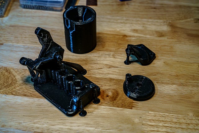
The Build
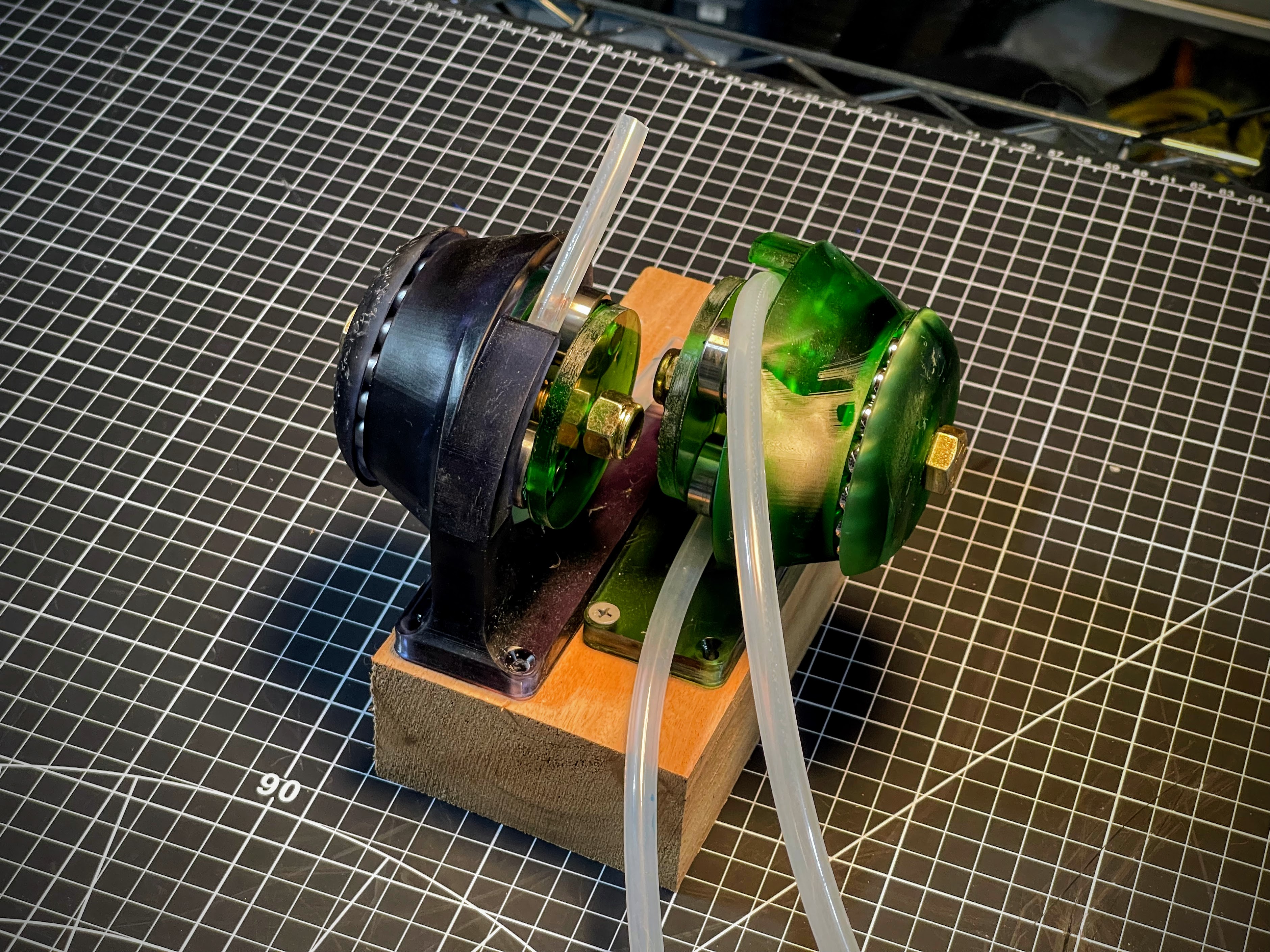
She ain't pretty (especially after a good while of getting knocked around), but the pic above shows the dual pump setup I rigged up for my testing needs. I was VERY pleasantly surprised that, other than a tweak to the hand wheel, these things worked pretty damn well!

I decided upfront that I was going to go with a resin printed build, because I thought the high stiffness and good surface finish throughout the 'pinch region' would give me a better chance. Since I was already going to have the good surface roughness, I might as well also integrate the main bearing into the printed parts.
In the image of the model, below, the Stator is the part shown in green, and the Rotor is shown in blue(ish.) Riding on the rotor are roller skate bearings to provide the contact with the tube. Race 1 has v-grooves on both sides of the race, providing the main constraint for locating the rotor, and Race 2 has a v-groove on the Stator, but only a single plane of contact on the Rotor side. This keeps from over-constraining the bearing.
 |
 |
The absurdly overkill bolt running through the center is a real showcase of "using what I had on hand" :) in that these were the only bolt/nut sets I had on hand with the length I was looking for.