Like a lot of people, I love me a 3d printing time lapse. I've experimented with a few different options over the years for capturing them, but I've struggled to get a camera mount for my Prusas that I was really happy with.
But I think I may finally have something that'll do the job and hold up for a while! And all it took was leveraging some generative design and metal 3d printing....I MAY have gone a smidge overboard on the fancy tools for solving a problem that I'm sure has already been solved a good many times over, but I had me a lot of fun in the process! :)
Among my previous attempts, some of my favorites have been those that are shot from a perspective that is locked to the part, and since my main printers are Prusa bed slingers, that means they have to be camera slingers too. Unfortunately, the combination of the heated bed and a cantilevered plastic arm have proven to be...sub-optimal. The heat from the bed, even well below the glass transition temp for the material, is still enough to really accelerate the creep, and they tend to get a bit droopy pretty quick.
So, when PCBWay reached out and offered me some free parts if I'd feature those parts on YouTube, and then mentioned that included their metal 3d printing services....well, it seemed like a good time to try again!
To ratchet the overkill up a notch further, I figured this was definitely a task that called for using a generative design tool to get some lightweight design options
Design
Generative design, and it’s close cousin, topology optimization, combine some form of simulation, like finite element analysis, with an optimization algorithm to produce geometries that can maintain stresses and deflections within limits while using the bare minimum of material.
What I really love about using generative design tools, in addition to the cool shapes they make, of course, is that I feel like they force me to focus time up front on defining my requirements.
Things like:
- What is attaching to what, and where. - “The interfaces.
- Do these interfaces have to have any specific features on them?, “required geometries”
- What are the loads and constraints I think these interfaces will see? - “Loads and constraints”
- Any ‘keep out’ areas for things like tool access, cable routing, or any moving parts need clearance? - “Keep out zones”
And all that kind of fun stuff.
I feel like it pushes me to maintain more of a ‘big picture’ perspective on the design in a way that I think is great.
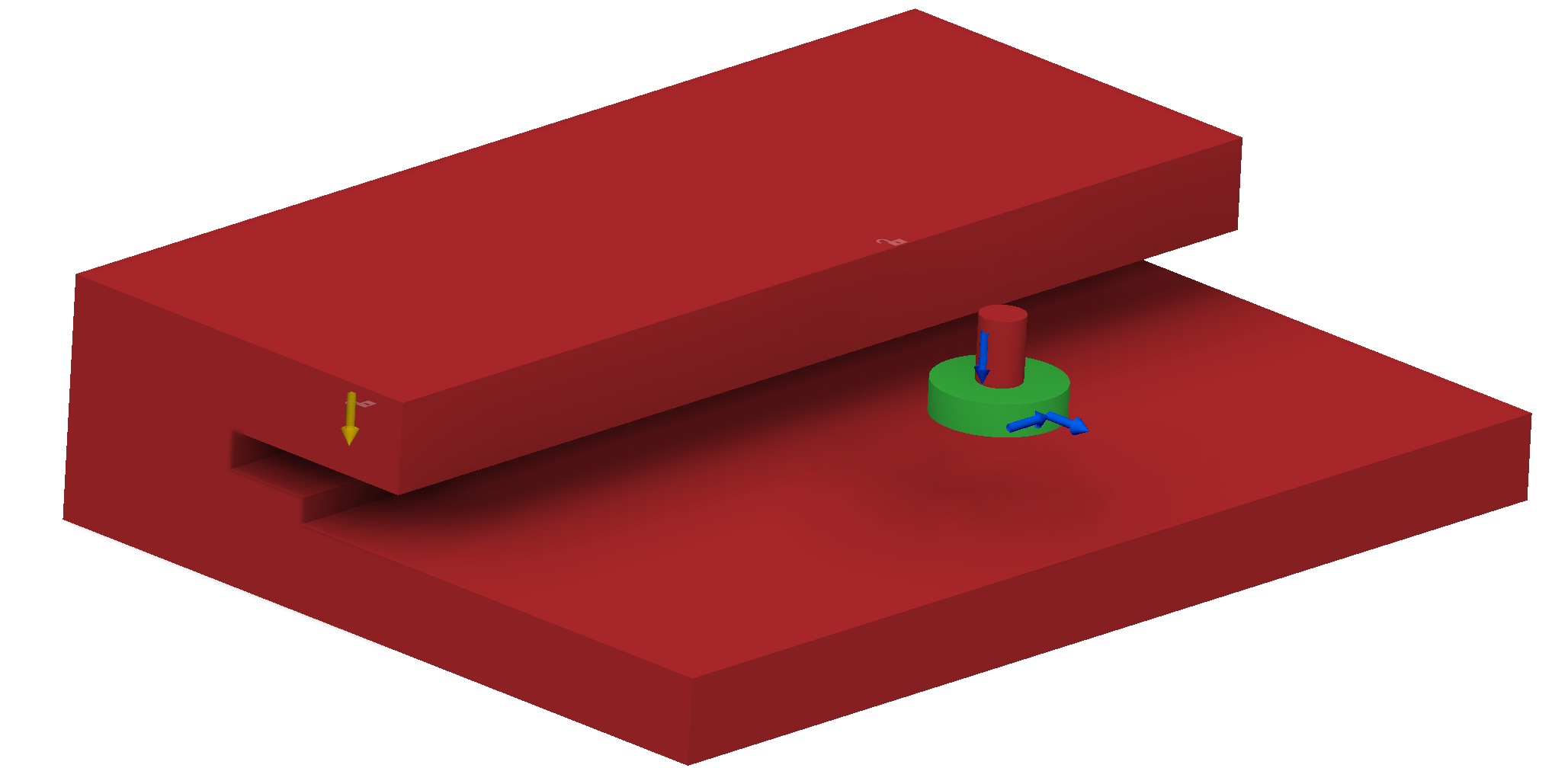
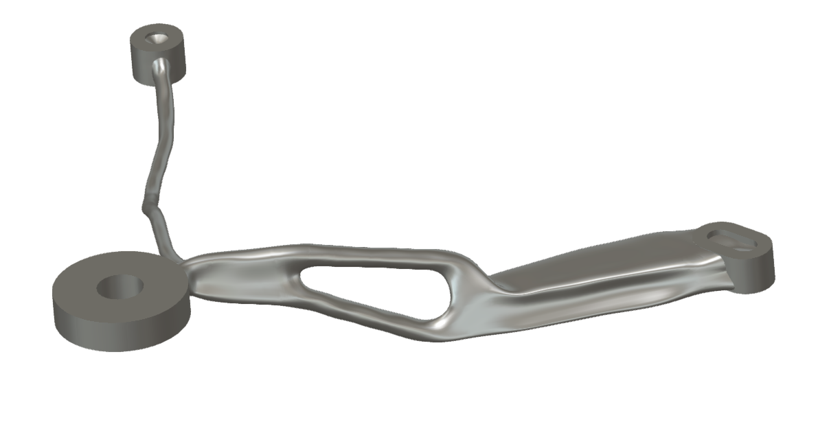
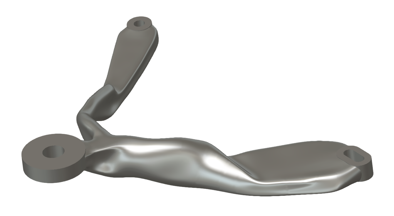
Taking a look at the screenshot showing what my end of the CAD for the camera mount looks like, we can also see that it makes for some just lovely model files :)
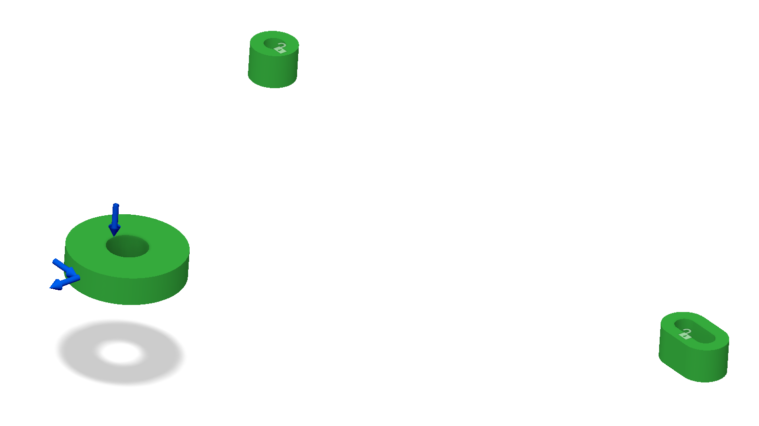
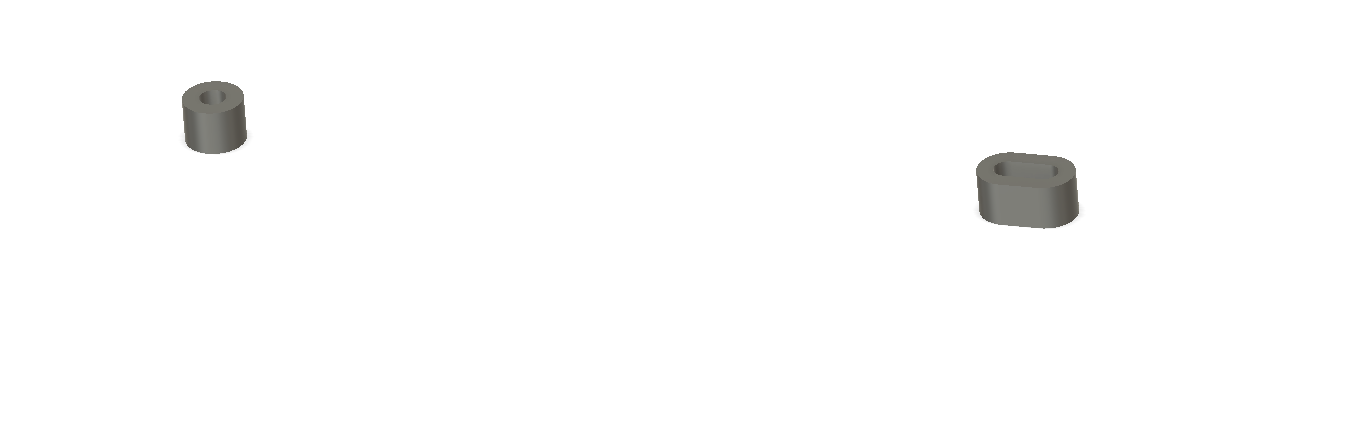
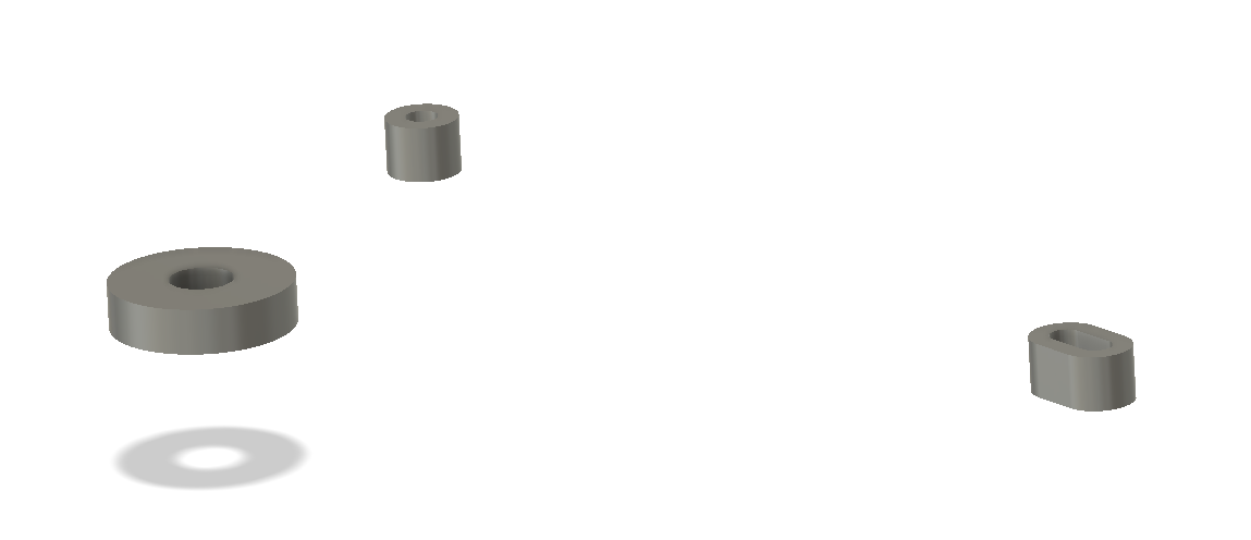
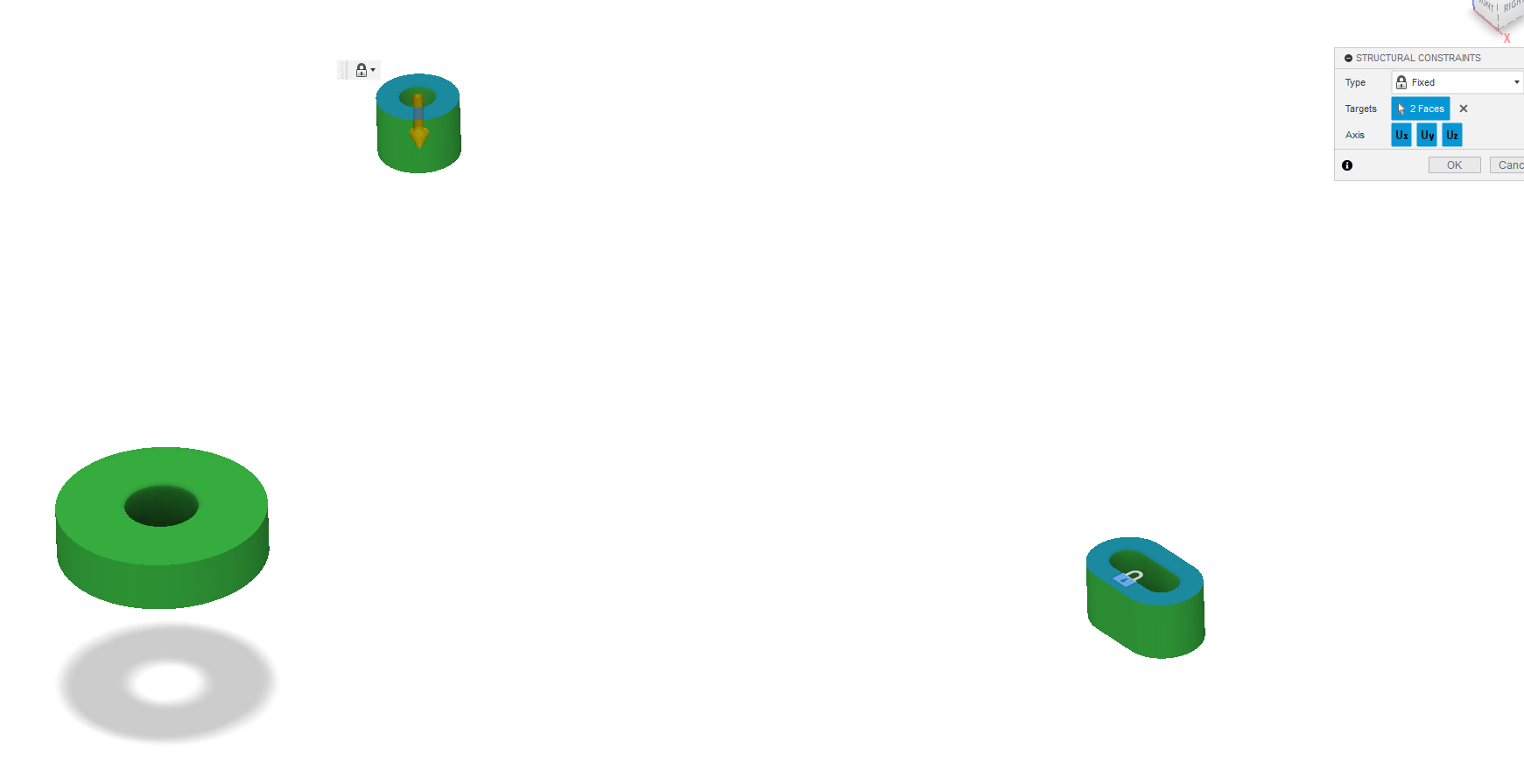
So what is it we're looking at in the above? Let's start by taking a look at the 'keeper' geometries. These are the three green bodies shown below. The larger one being the camera mount interface, and the two smaller ones are the mounting interfaces to the printer bed.
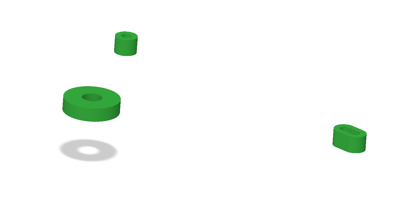
The bed mount points are intended to be direct replacements for the 6mm long, steel spacers that separate the bed heater from the Y-carriage on the Mk3.
 |
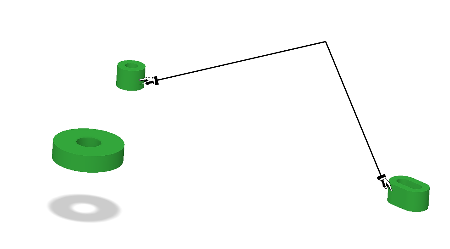 |
Unfortunately, the center-to-center spacing between these spacers aren't symmetric, so I slotted one of the mounts in the design to allow me the flexibility on mounting.
The only other 'keeper' geometry is the camera mount point, which is basically just a beefy 1/4-20 washer.
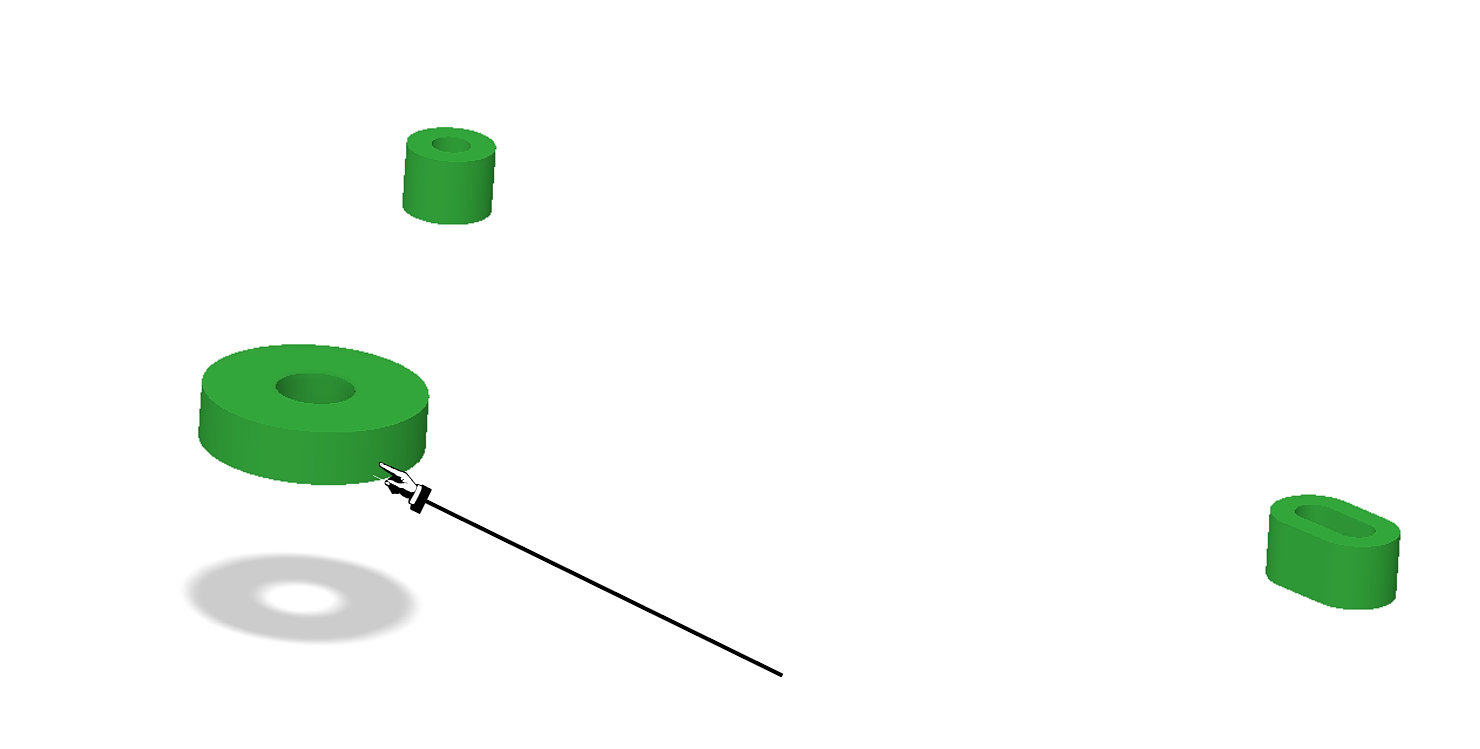
It would have been cool to integrate the GoPro mount into the printed part, but because of my pretty limited experience with metal printed parts I wasn't confident enough in getting that to come out correctly without a few iterations. Plus, sticking with the 1/4-20 mount makes it compatible with a lot of other camera options, should I want to swap out the GoPro for something else down the line.
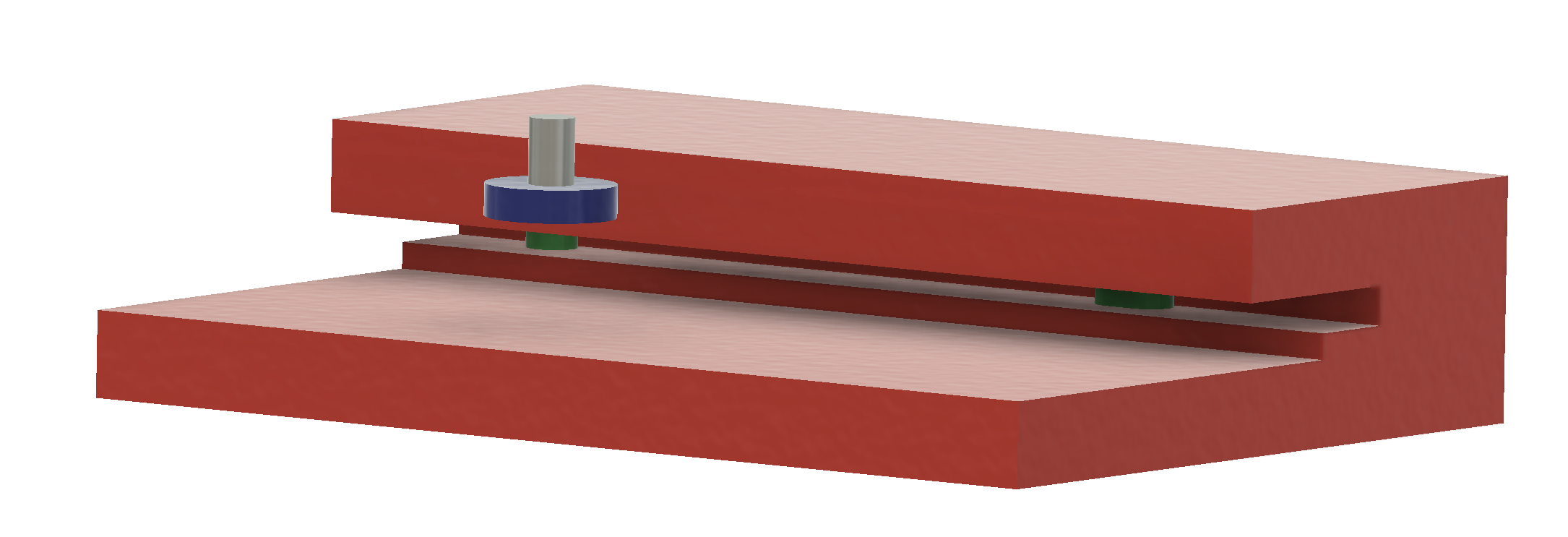
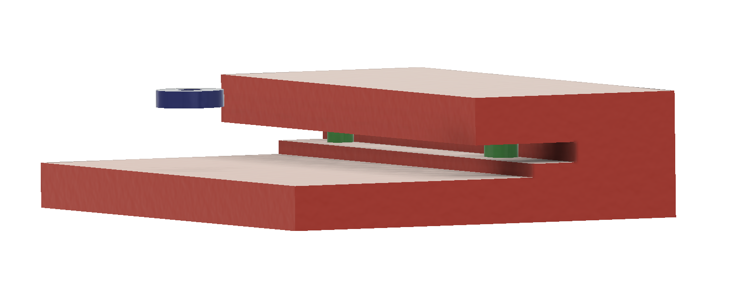
So, interfaces/keepers out of the way, what was that big ass red thing? The geometries that the software shows in red are the 'obstacle' geometries, which I tend to refer to more as "keep out zones". These are where I'm telling the software that it's not allowed to place material.
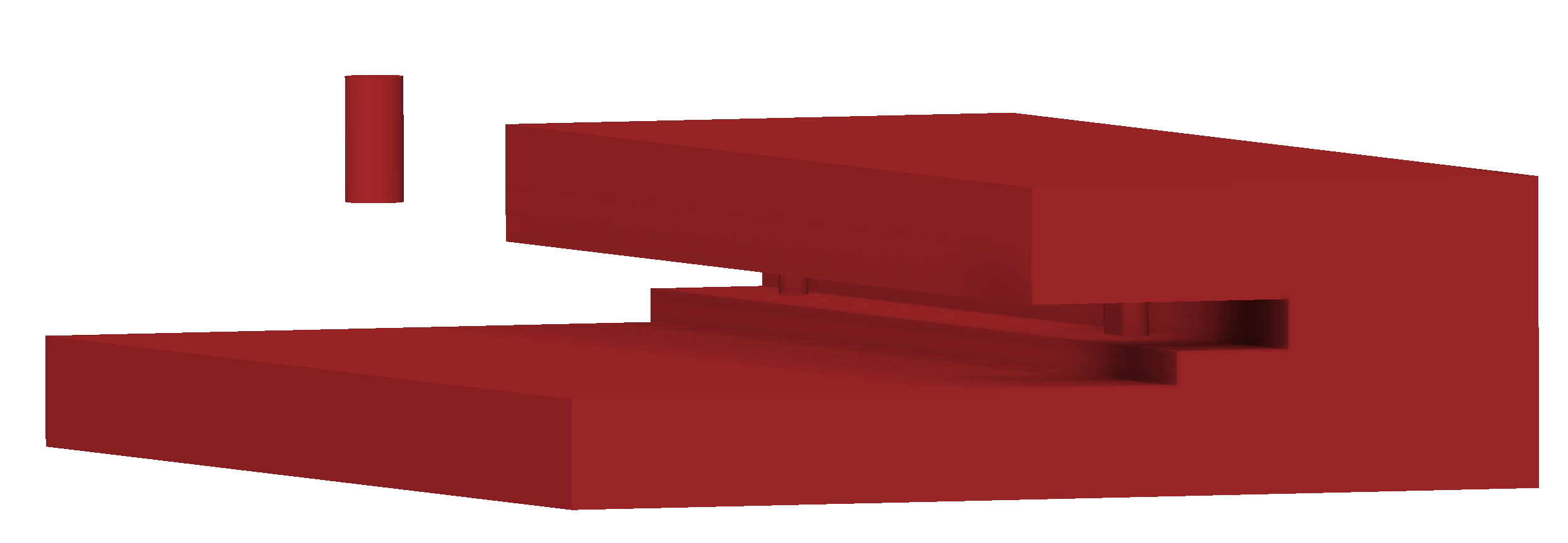
The big, blocky bit provides the keep out areas that cover the heated bed and Y-carriage parts above and below the spacers. The only other additional bodies are the posts that sit inside of the clearance holes for the fasteners that will need to go through my mount points.
And that's pretty much it for the 'CAD' portion of the design
Now that the base geometries have been defined, it's time to apply some loads and constraints to them.
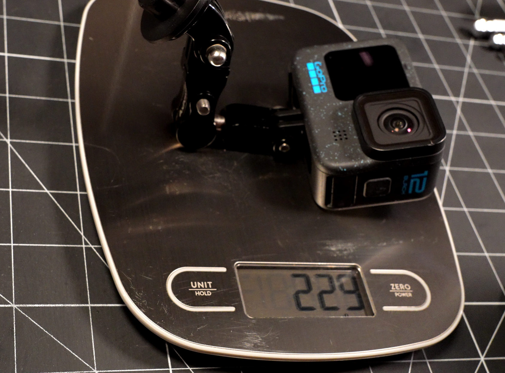
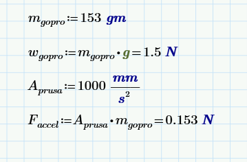
To get some estimates for the expected loads, I started by getting the mass for my GoPro and it's mount(s)....yeah, I realize the heft of these kind of wipes out the benefits of my optimized mount, but cest la vie.
I then estimated some accelerations I expect that mass to be subjected to and used some of that Newton goodness (F = ma) to get the forces. The accel limit in the Prusa Slicer software (which I'm guessing is the default, because I don't think that's one I've ever tweaked) is 1000mm/s^2, or 1 m/s^2. That's about 0.1g. So I rounded that up to about 1g for the Y, and I went with 2gs in Z to cover gravity plus some margin for the dynamic load. I also added about 0.5g to X, mainly just to ensure that it has SOME stiffness in this direction to handle some light jostling and such.
There are quite a few issues with how I've decided to do this, including the fact that this approach doesn't account for the additional offsets to the CG of the mass due to the GoPro's mounting. I decided to just add some additional margin to the load cases, in addition to the built-in Safety Factor in the solver, instead of creating a more 'accurate' loading scenario. While I still think this is a reasonable trade-off for this project, I'm hoping as I get more familiar with the software I'll learn better ways to structure these within a larger model, allowing some of this to be fed in parametrically...but we shall see
Now that my loads are applied, it's time to set some constraints. I set both of the bed mounts to be constrained in both Z and Y, but only the non-slotted one was constrained in X. This wasn't strictly necessary, since technically the slotted one is also constrained in X due to the friction of being sandwiched between the heated bed and carriage. But I wanted to also ensure there would be some stiffness in the part along this axis, and if it throught these mounts were both rigidly constrained, it could conceivably have the whole mount extend from only one bed mount and still satisfy the criteria.
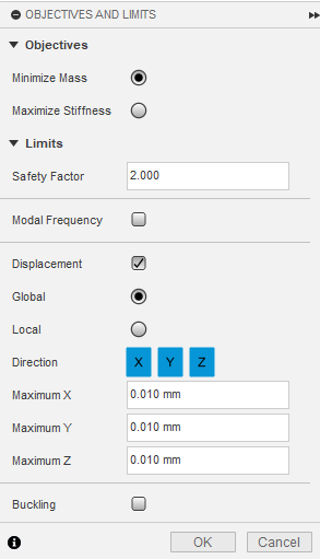
Now that the loads and constraints are set, all that's left is to configure the settings for the solver. Starting by setting the 'Objectives', shown below. I left the Safety Factor as 2, but given the low loads we're talking about here, I'm guessing it's likely to hit the minimum thickness limits before getting anywhere close to this (this minimum thickness parameter can also be changed, but in a different setting window). I opted to also require displacement limits in addition to the stress limit. The thought here was that I don't want my camera bouncing around on me as the bed whips back and forth. So I targeted a somewhat ambitious 10 microns of max movement on all axes...this is only going to make that Safety Factor even less important :)
Next is setting up any specific considerations for the manufacturing process you intend to use....this is the area of these software tools that I most hope to see advance significantly in the coming years.... Although it does 'support' multiple fabrication types, in my (admittedly limited) experience, it is not particularly good at actually incorporating Design For Manufacture into the solutions. But, this is where I can set things like overhang angles and minimum thicknesses.
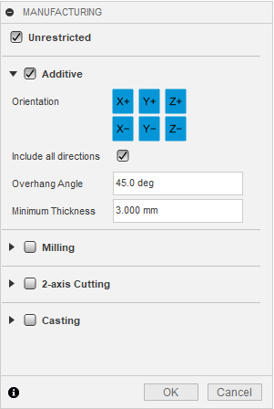
And, last but not least I just have to set a material, if not already configured in the solid model. I selected the only aluminum flavor Fusion lists under its Additive Materials list (AlSi10Mg). I'm not sure which specific alloy PCBWay uses, but I'm assuming it will be similar. I know that for the metal AM that I have worked with previously, they tend to use alloys that I've never heard of but that are well-suited to the process.
--Update from the future, I went and looked on PCBWay's site and they are indeed using this AlSi10Mg alloy. So tip-o-the-hat AutoDesk :)
Now that everything's set up, all that's left is to hit 'submit' and wait....and then wait a bit longer...it's not the fastest thing...but then again, neither am I.
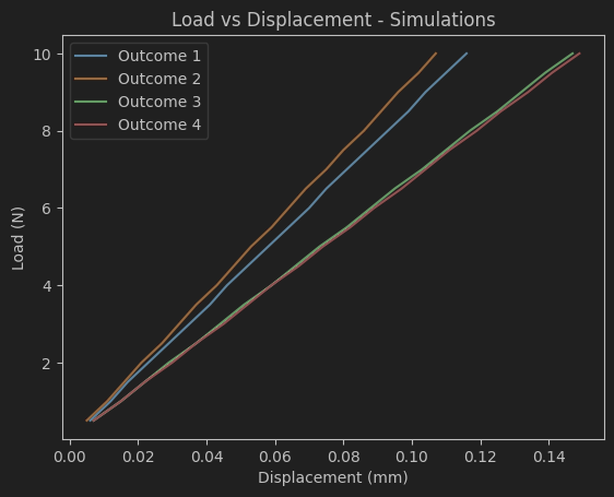
Although, it is kind of enjoyable watching as the solver iterates through, getting ever-cooler looking designs. And when it's done (assuming it converges) it reveals all of the different variants that resulted. My assumption is that each of these "Outcomes" represents some difference in starting conditions in the solver, but it's not obvious exactly what these changes are.
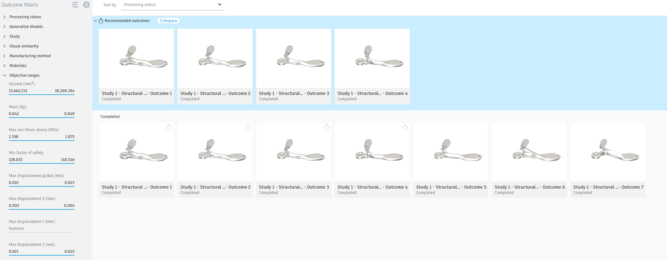
But, regardless of how it got there, we now have our parts to do with as we please! From here, I could export them to a Design environment, to modify or integrate into a larger design. But, since one of my goals with this project is to look at the generative design to metal printing pipeline, I just exported them directly to STEP files to send em off for printing!
Ordering
A huge thank you to PCBWay for sending me these parts for free! But even without getting them for free, I am really excited by the thought of having access to metal printed parts like this! The only metal AM parts I've had access to in the past were through my day job, and even internally they cost at least $1k just to get them to put the powder in the machine. I was blown away when I went through the quoting on these and saw that would have only cost me less than $40 each. And they aren't paying me to hype this, I promise, just the comp'd parts for credit on YouTube. I just genuinely think it's wild that garage tinkerers like myself can now get these kinds of parts for less than the cost of going out to dinner....the future is awesome :)
But anyway, I digress. I took the four 'Recommended' designs from Fusion360 and uploaded them to PCBWay's quoting system. I clicked on Titanium and tried desparately to justify to myself why I needed it. After failing at that, I clicked the aluminum option and skimmed the other options, but the defaults all seemed ok by me. So I sent em off for fab and got back to work on my Mechanical Tester to try to have it ready for some fun once the parts arrived. More on that below.
....two....weeks....lata....ish
Measuring
Mass
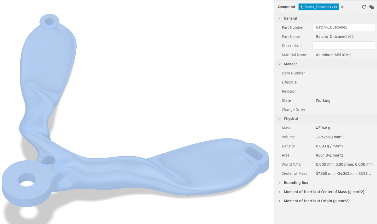
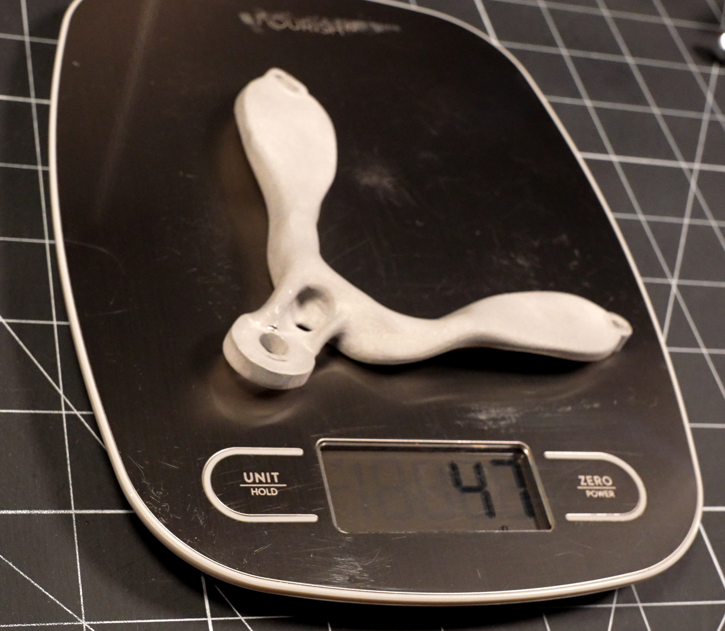
|
47.9g
 |
 |
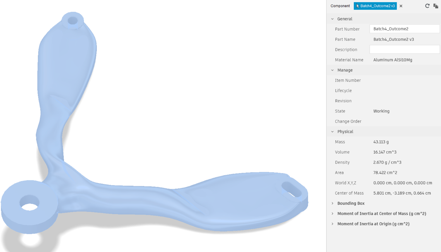
|
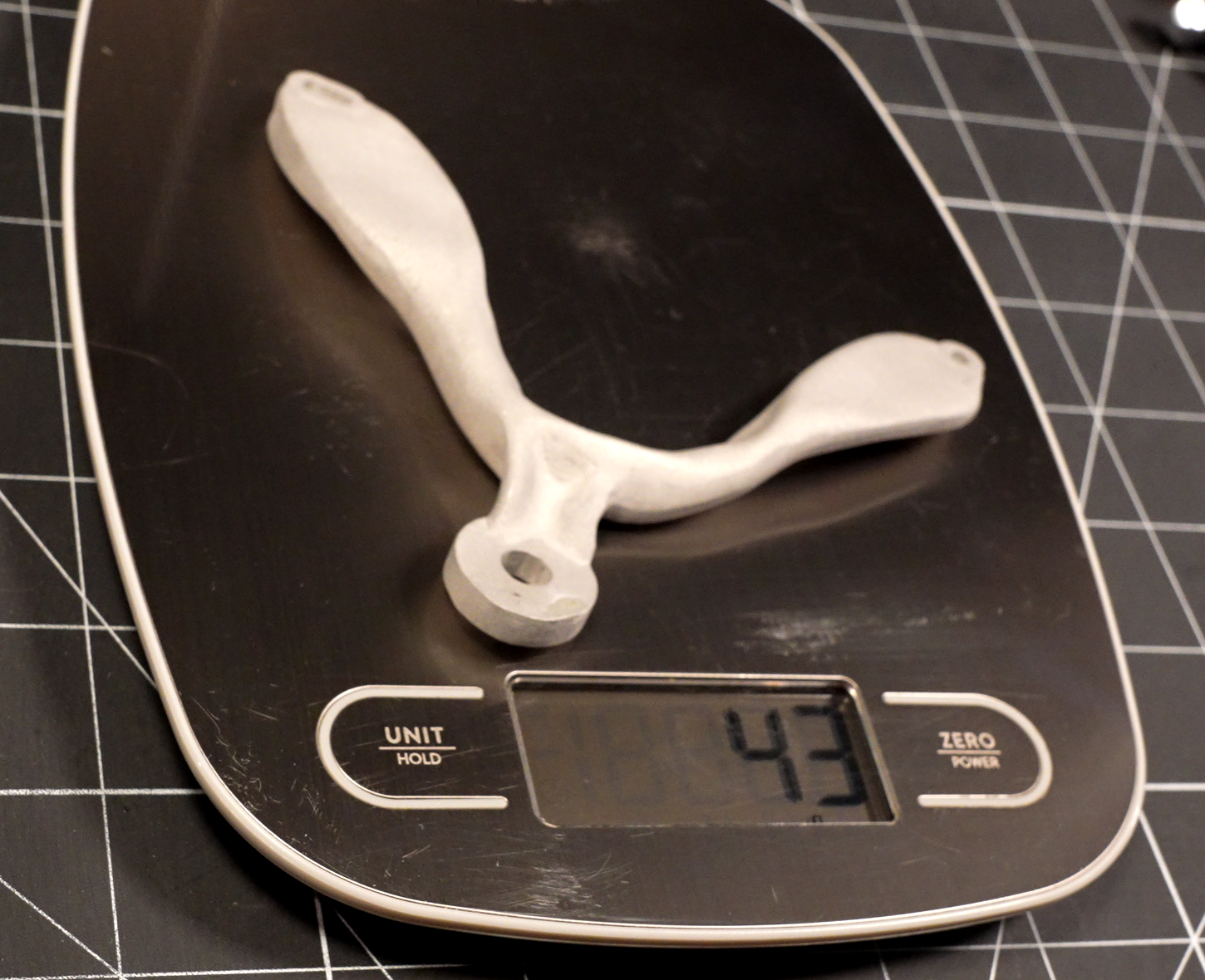
43.1g
 |
 |
|
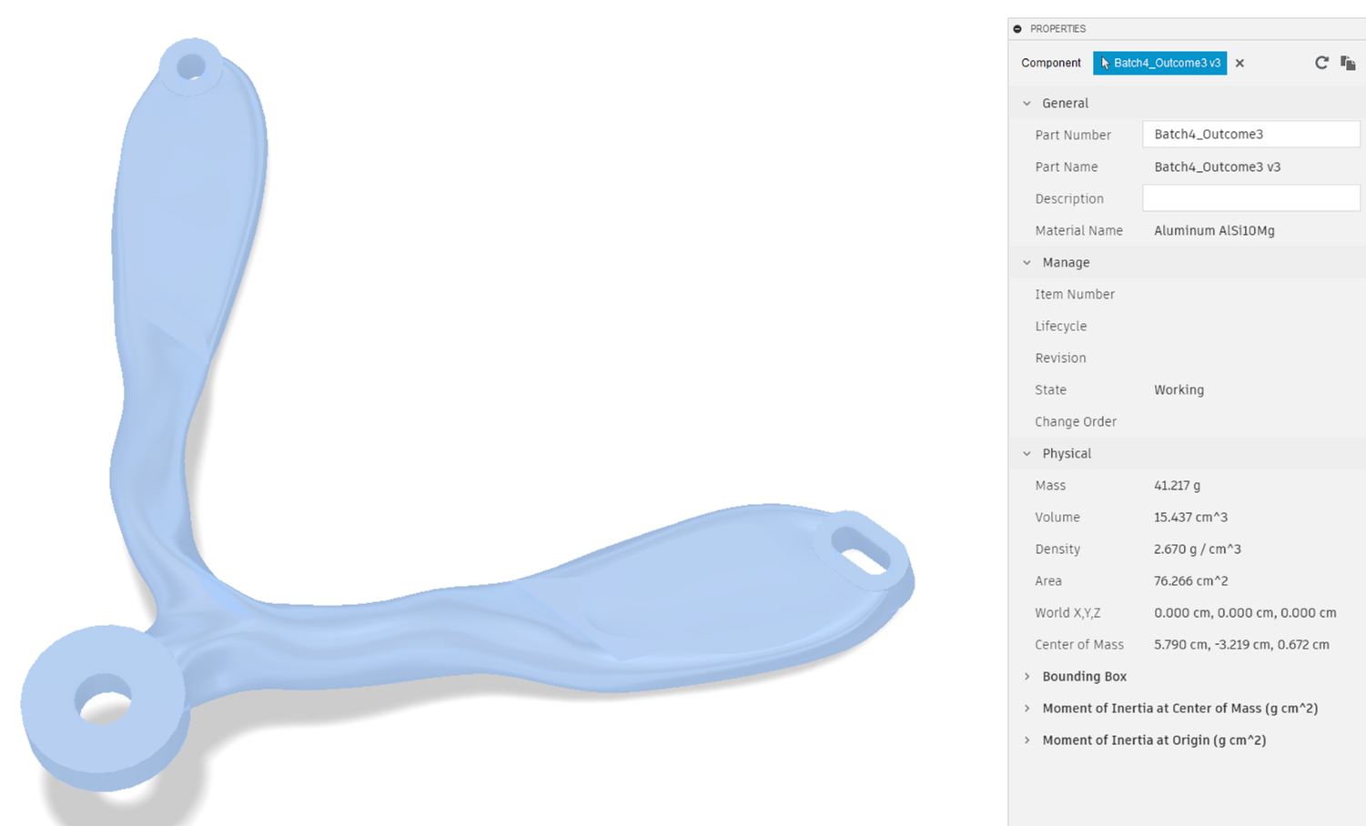
41.2g
 |
 |
|
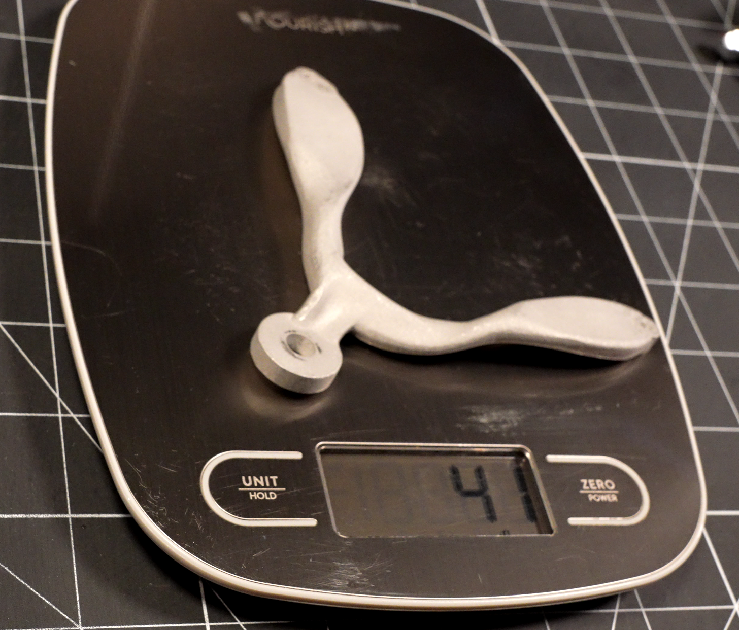
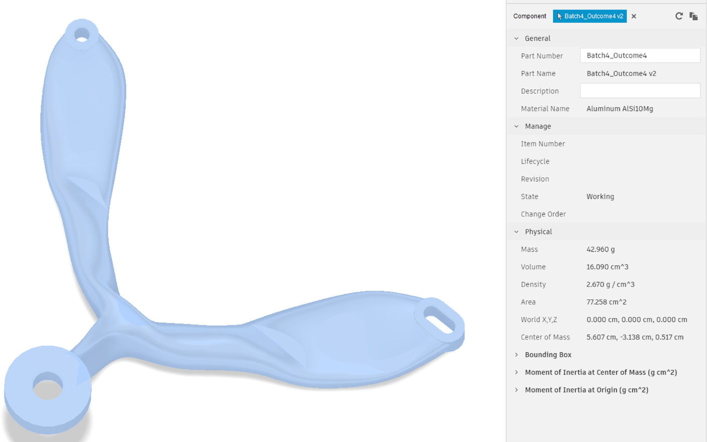
43.0g
 |
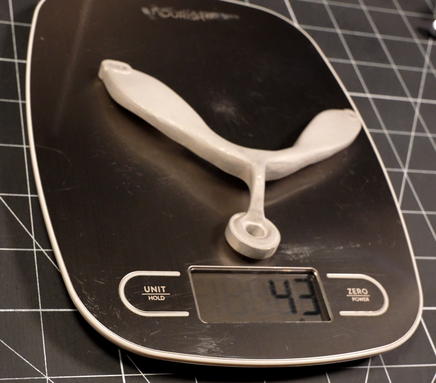 |
Wow...I'm actually pretty surprised by how closely the actual masses came to the predicted. My take aways from this are:
- There is not substantial porosity in the part. This does not necessarily mean that all of the powder was fully melted, but since even the high packing factor powder mixes used in these processes has a few percent void space, it does bode pretty well. Bases on the bit of deformation visible on a couple of the camera mounts, my hunch is that they have the laser powered cranked up a bit. That will give some margin on getting density, but it makes me wonder what sort of issues they may have with risidual stresses in some parts and how they're handling that.
- There is not appreciable over or under printing increasing the total volume of material.
Of course, it's possible that some combination of the above things could just be canceling out, but the odds of all four parts being so close to nominal makes me think that's less likely.
Dimensional
I by no means did any sort of 'real' inspection, but I did put the calipers to a couple of key dimensions for each part to compare to the nominal "keepers".
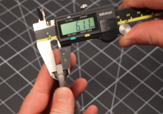
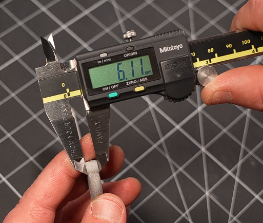
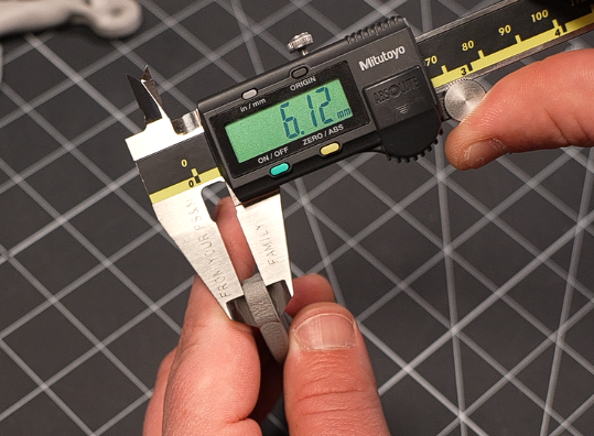
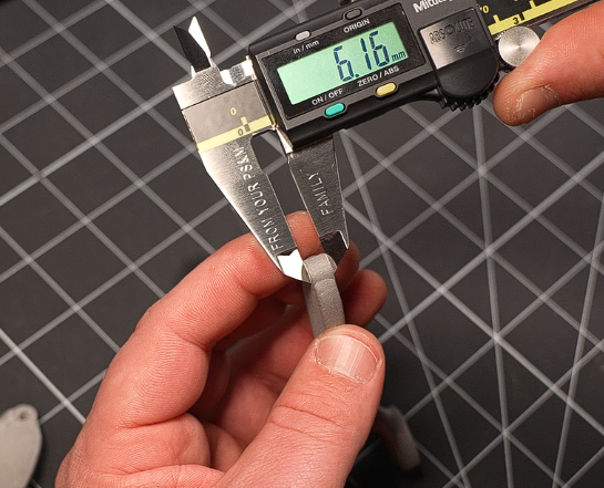
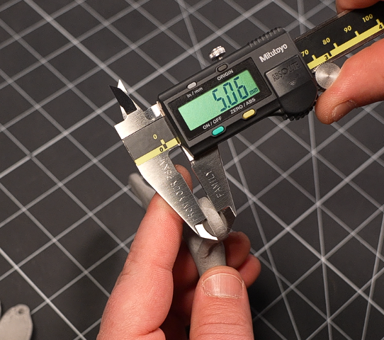
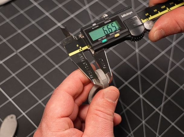
The one that's most likely to impact performance is the thickness of the bed mounts. The existing spacers are nominally 6mm....well crap....as part of putting this write up together, I discovered I somehow messed up here! Turns out, these are actually nominally 5.5mm (mine all measured between 5.52 and 5.54 millimeters). Well damn, I guess this speaks to how good bed leveling is! I've now made several parts with these mounts installed, and apparently they aren't off by the 0.1 - 0.2mm that I thought they were (based on the measurements shown in the pictures below)...more like between 0.6 and 0.7mm. For the models that I upload to sharing sites, I will update the model to reflect this 5.5mm length.
But anyway, my poor quality control issues aside, what I wanted to show with the below was supposed to be that it does indeed appear there is a little bit of overprinting, about 100-150 microns for the thicknesses of the bed mounts.
 |
 |
 |
 |
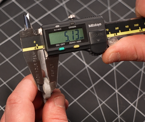
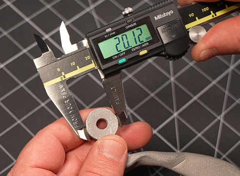
Taking a look at the camera mount, we see a comparable amount of overprinting. The extra thick boyy down in the bottom right isn't an overprinting issue. I decided not to add obstacle geometries on that face, and the solver added an interesting little ring of material here. Since the only thing touching this face will be a fastener head, it isn't an issue. But next time I'd probably go ahead and add the blocking geoemtry just so it can be sized for a specific fastener length.
 |
 |
 |
 |
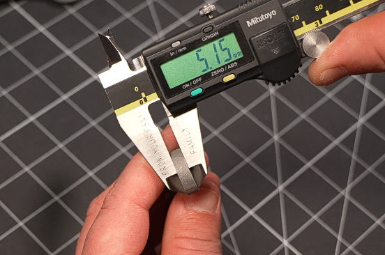
One additional dimension I'd be curious to take a closer look at is the diameter of the camera mount, but I've noticed that they all have at least some level of circularity...challenges. Unfortunately, I'm not really equipped to get a good measure on that, so I'm just going to save that for another day. But as you can see from the one measurement on "Outcome 4" below, they did come out generally close to the nominal.
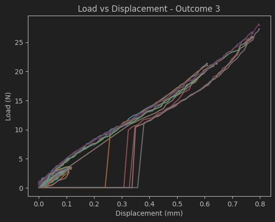
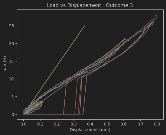
Mechanical Testing
This is, quite honestly, the part of this project that I've been most excited about....it's also the part that definitely still has the most to go before I'll be happy with it.
While I've been playing with generative design tools like the Fusion360 one that I showed above for a couple of years, I haven't had the opportunity to get real data to compare the software's prediction on the strength of the part to that of its real world counterpart.
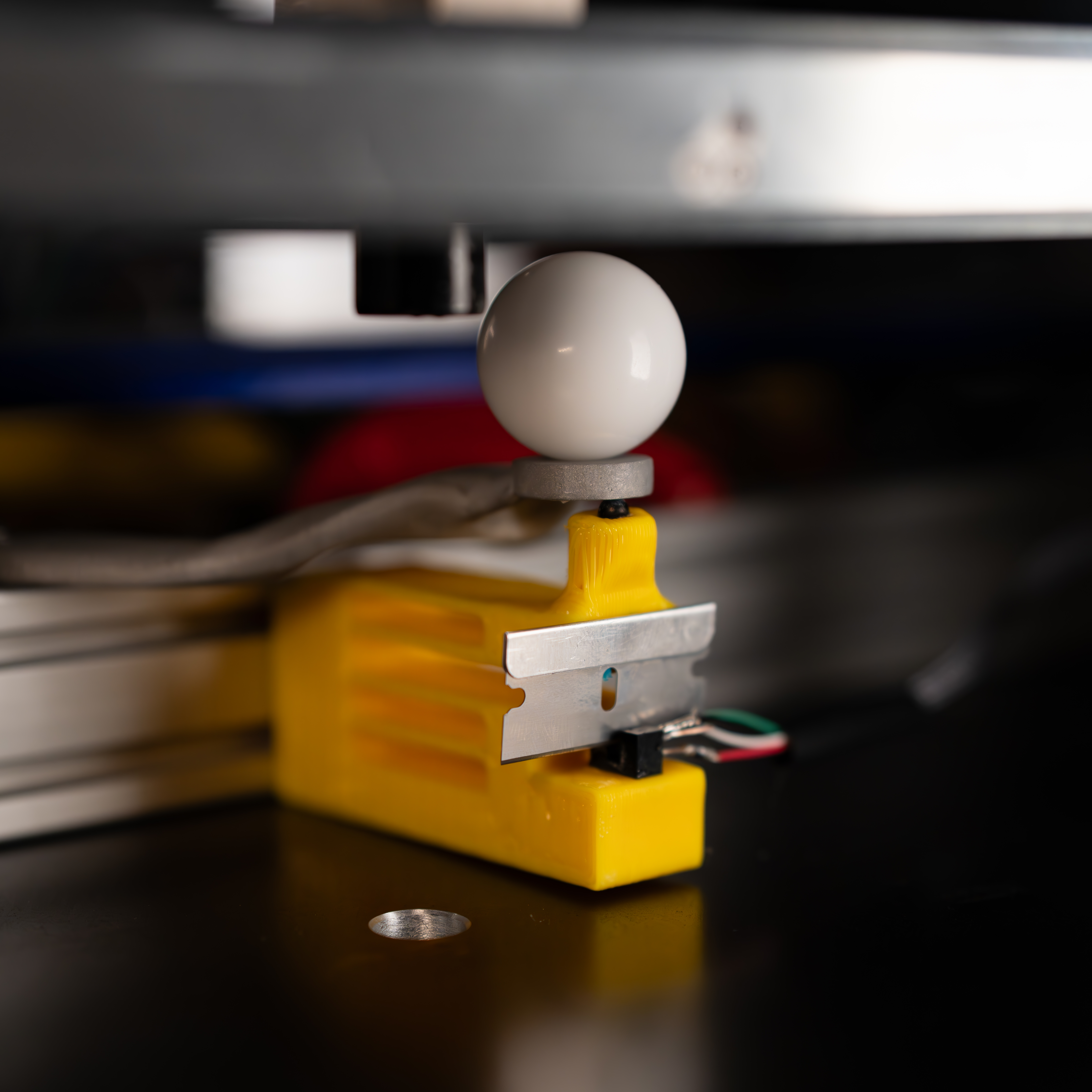
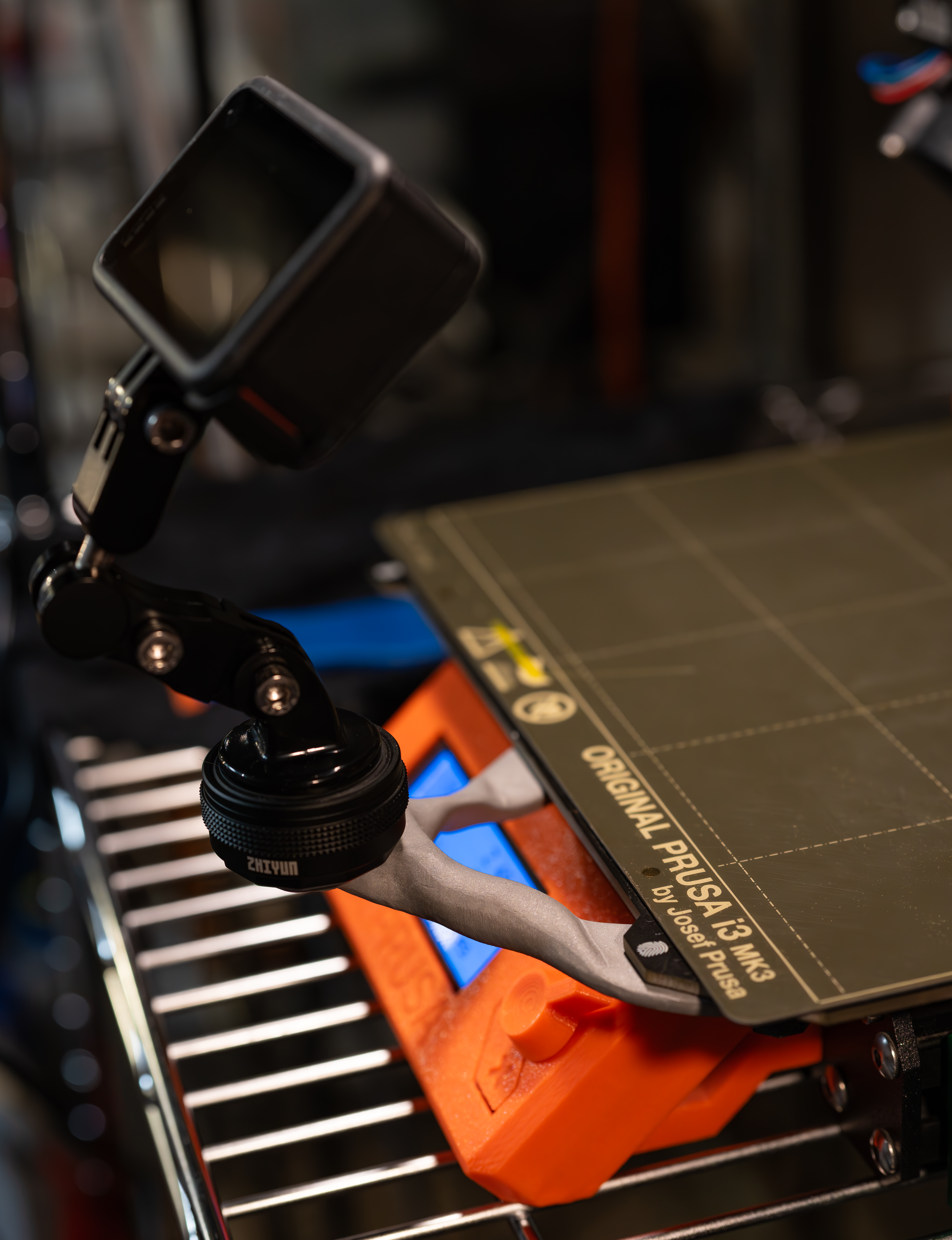
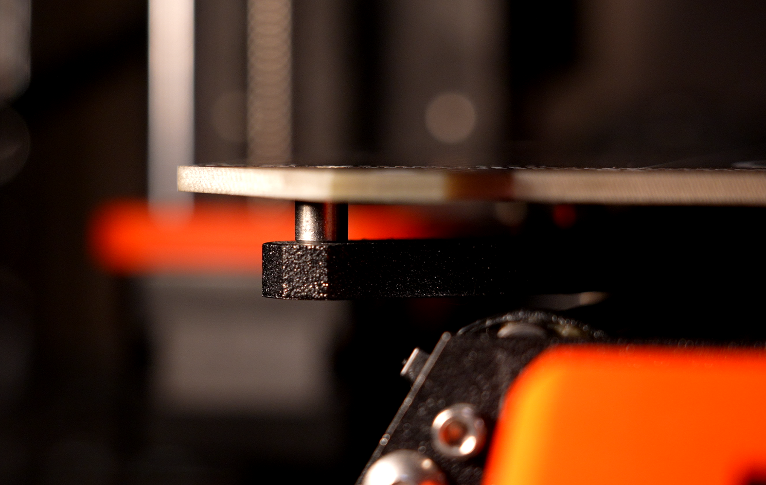
The metric that I'm equating to "strength" here is actually stiffness. That's something I can measure fairly one-to-one between the simulation and the physical tester. But to make that possible, I first needed a way to measure the deflection of the part as I apply load (the Mech Tester thus far has only been instrumented for load). So I rigged up a displacement sensor that mounts underneath the mount in the tester (that's that hideous yellow fella with the super-safe razor blade stuck to it.)
The big delrin ball is just there to try to keep the force applied as close to a pure Z-axis load as possible, since the ball can't transfer a moment (other than from whatever friction there is between it and the aluminum parts on both sides).
Design Notes
2024/02/14 - Initial stab at it
To start, I'm going to see what I'd get if I design for a GoPro, but I don't really intend to go with anything larger than a Raspberry Pi HQ camera. So we'll see how it looks with a GoPro mass as a conservative first pass.
According to the GoPro site, the GoPro 12, with battery, weighs in at 153g.
For the model, I started with just defining the contacts for under the bed. The right one is slotted to allow the bracket to be used on either the right or left side. And, frustratingly, these are not symmetric for some reason. So it is slotted to allow for either the 105mm (left) or 110mm (right) position.
I added in the disk for the camera mount. It's basically just a bit 1/4-20 washer. I offset it 75mm from the centerline of the stage fasteners and with its bottom surface 15mm above the bottom of the bed spacers. This should put the plane of the camera mount 10mm above the print surface. This seems like a reasonable spot for a nice wide angle timelapse.
I then added in a first swing at a keep out zone. I think I covered everywhere needed, but I'm sure I'll be wrong :)
I set one face of each space as fixed.
I approximated the load of the camera mass at 2N.
To get a rough number to use for the side loading due to acceleration, I got an accel rate of 1000mm/s^2 from a quick perusing of forums. So I put that with the 153g GoPro mass and got 0.153N....to be fair, I put it in MathCAD before I knew the number would be as easy as 1000...
Again, to be conservative, I'm going to round this up to 0.5N. And I will apply two load cases, one in each direction of Y movement.
I'm ultimately hoping to send this to PCBWay to take advantage of their metal AM, and have this printed in Al. So I set the only Al option in Fusion's additive materials library and started the solver runnin!...now I wait...
First batch of solutions are done! Overall, they look pretty good, other than I forgot to include keep outs inside of the bores. I'm also a little worried about that spindly little link to the left mount.
I added some material to the keep out for the holes. I also changed the constraint for the left side mount to be only constrained in Z. My hope is that this will force a little bit of cross-bracing.
I also updated the 'design objectives' to include a maximum deflection criteria. I set it at 0.01mm globally, which may be a bit too optimistic. So once I see what comes out I can adjust if needed.
Well I didn't get the cross brace that I was hoping for, but this definitely looks abit more substantial:
I'm going to call it there for today, but I exported two of the results from that last series to see how a quote looks.