
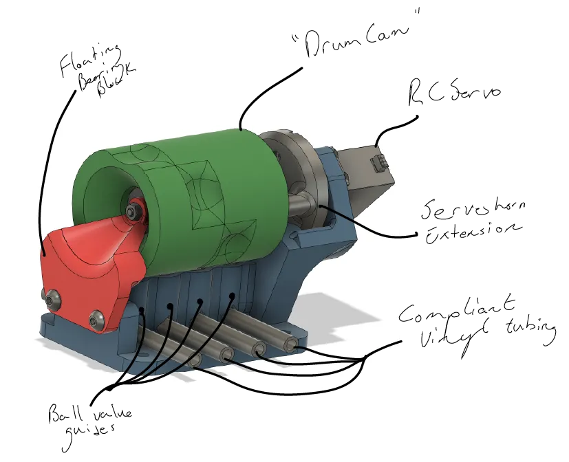
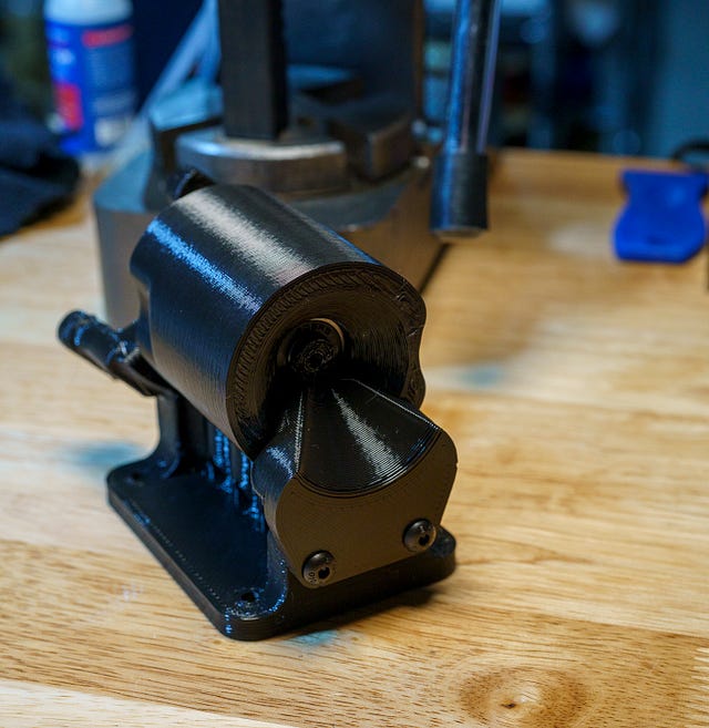
This design is for a digitally-controlled, four ‘channel’ valve assembly. I designed this specifically for the application shown in the picture above, where I wanted to be able to controllably dose from individual reservoirs to individual target plants. By combining a couple of these valves with a peristaltic pump, I could supply four plants from up to three reservoirs.
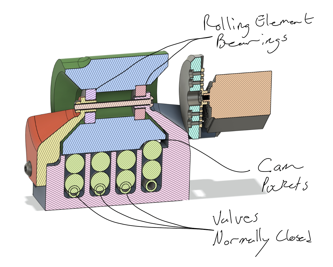
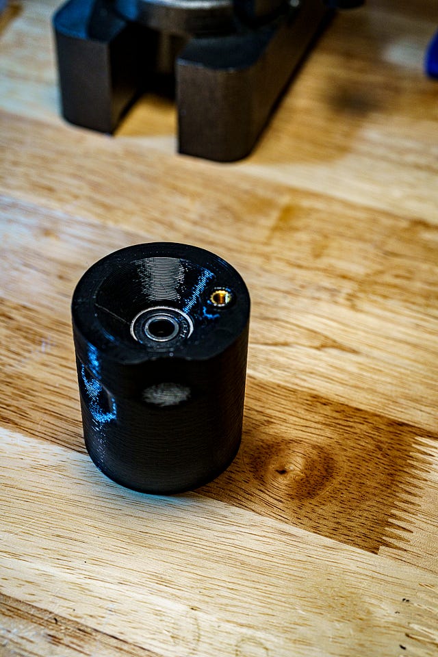
The valve works by the camshaft pushing steel balls against the tubing passing through the valve. The channels are closed except when the cam rotates such that the ‘pocket’ for that channel is rotated such that the ball can lift and release the tube. The video below shows one in action.
Design Overview
A good friend (and far better engineer than I) was kind enough to record a full Design Review video for this…but technical difficulties (aka I’m still new to OBS Studio) meant none of his audio was captured…oops…I am curious if people would actually be interested in these sorts of Design Review videos, any opinions or suggestions would be much appreciated!
Parts List
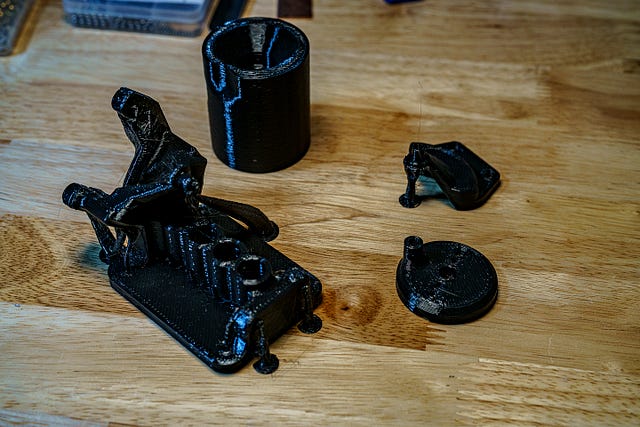
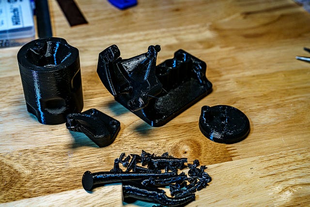
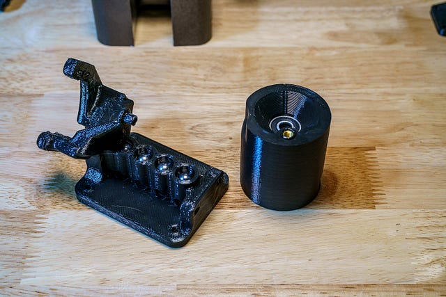
Printed Parts:
I’ve now made a handful of these valves, and I’ve made all of them from Overture PETG. I generally like working with PETG, and it holds up well for these. The only downside is that PETG does wear a bit at the contact between the drum and the steel balls. I haven’t experienced any problems, but I anticipate it will lead to progressively worse sealing over time. I didn’t want to use PLA because I expect mine to see a fair bit of UV exposure, but I’d be quite curious to hear what else folks try and what works well.
- DrumCam.stl
- Housing.stl
- CamSupport.stl
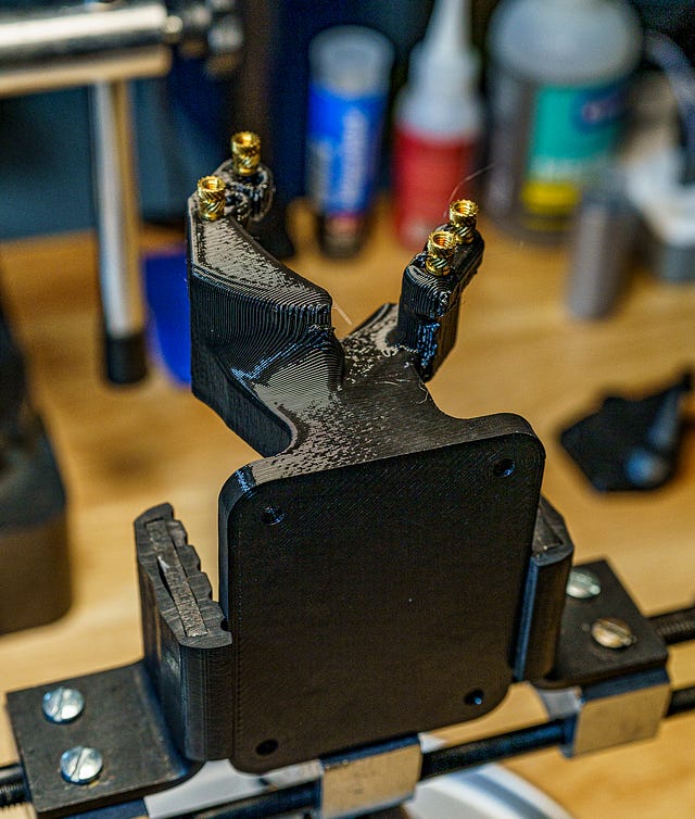
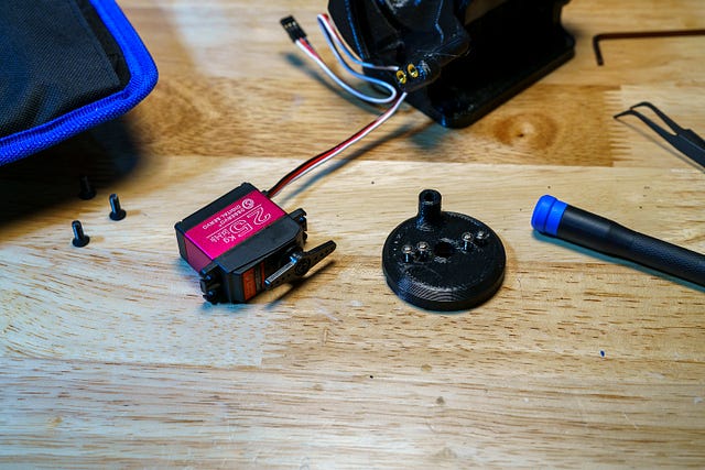
- ServoInterface.stl

Please note, I sliced/printed these prior to the release of organic supports in Prusa Slicer, of which I am a very big fan. If I were printing these today I would use organic supports…and actually, I just realized that for the build I did in the images below, I did indeed slice it with them. But the screenshot I saved, is the screenshot I saved!
COTS parts
- (Qty 2) 608 2RS Bearings — Aka skate board bearings. There’s not much demand on these bearings unless you’re putting yours in some weird/harsh environment, so any 8x22x7mm bearing should do fine.
- (Qty 1) DS3225 Servo — It was originally designed for, and still can be built with, an MG995 servo, but while it seemed to operate fine for several weeks, I felt like it sounded like it was loading closer to stall than I wanted.
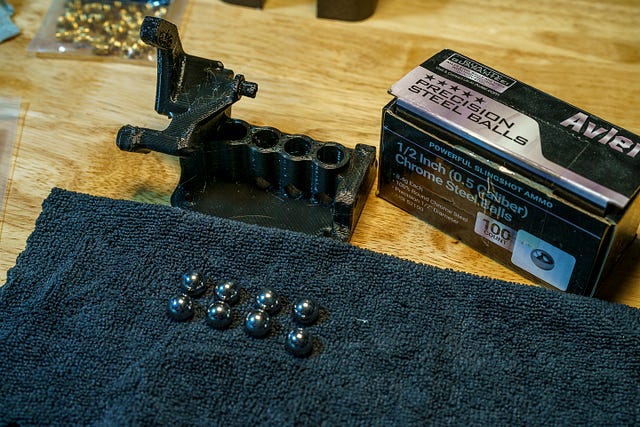
- (Qty 8) 1/2" or 12.5mm balls — I have just been buying these in different sizes recently, but you obviously don’t need 100 pieces for this project.
- (Qty ?) 5mm x 8mm Silicone Tubing — You’re looking for a compliant/soft tubing with the matching ID/OD. You would probably be fine (and maybe even get slightly better sealing) with a thicker wall, but at the cost of more Cam wear.
- (Qty 4) M4 x 8.1 Heat set inserts — You should be able to use any length of M4 insert, just make sure to choose the corresponding fastener accordingly.
- (Qty 1) M5 x 9.5 Heat set insert — This will be the load path from the servo to the camshaft, so just make sure you have enough thread engagement, but with it being M5, really any depth of insert should be fine.
- There are a number of options for fasteners, and I tend to just use assorted kits for each size, which is overkill for the few fasteners you’ll need for this. So I’ll list them here
- (Qty 4) m4 x 10 BHCS
- (Qty 1) m5 x 30 BHCS — could also sub this with an m4x30 and replace one of the m5 nuts with an m4 nut, but may want to also toss in a washer just to be safe.
- (Qty 2) m5 x 18 BHCS
- (Qty 3) m5 hex nuts
Assembly


This project is part of a collection of AgTech projects that I am working on putting together as an open source hardware project, JFS Agri. I am excited by the intersection of growing my own food and playing with tech toys :) if you’d like to see a summary of the projects along the way, I’ve started an overview page here. I’d love to find like-minded folks with a similar interest that are interested in collaborating, generating data, or just chatting about AgTech!