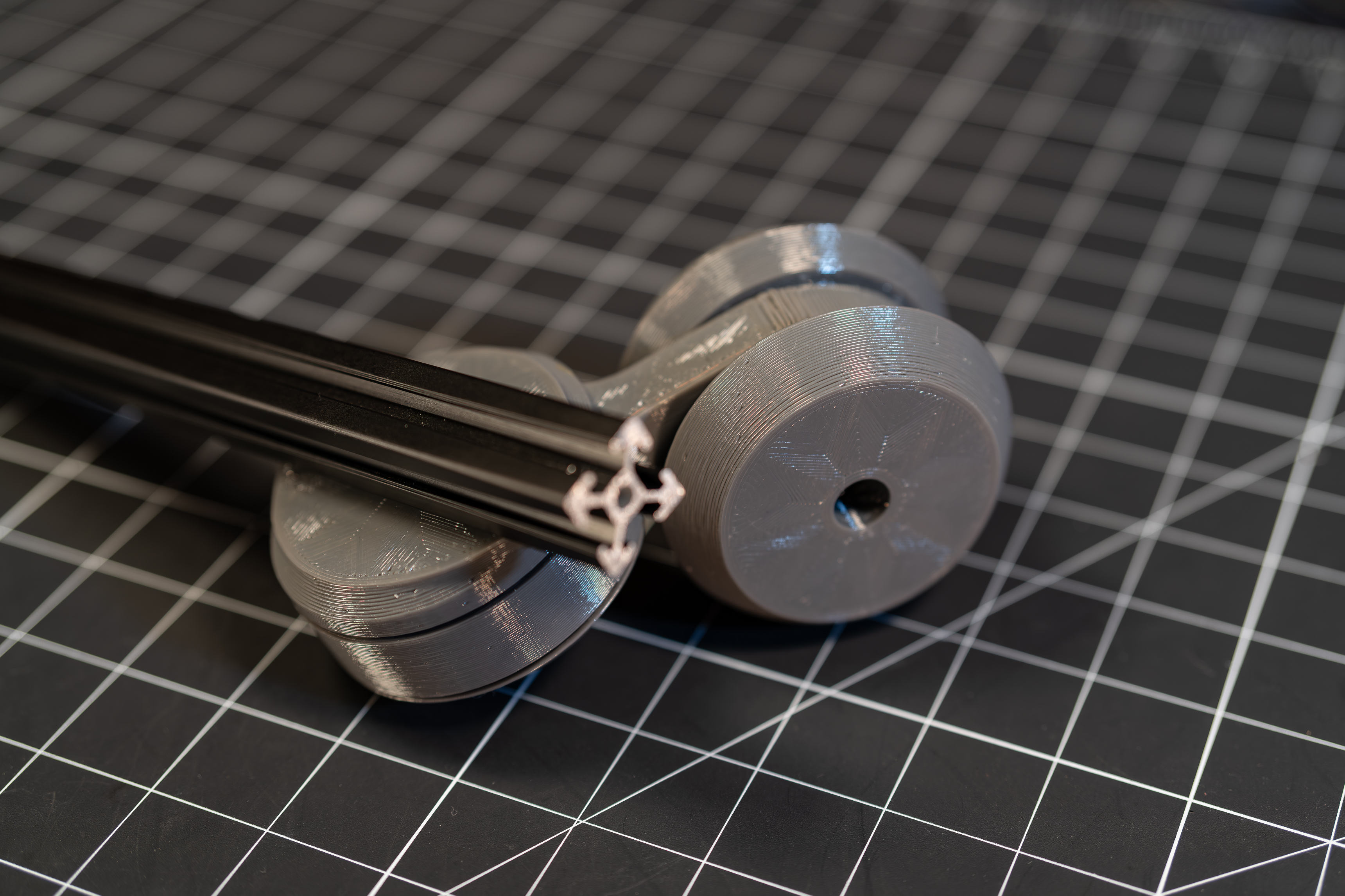
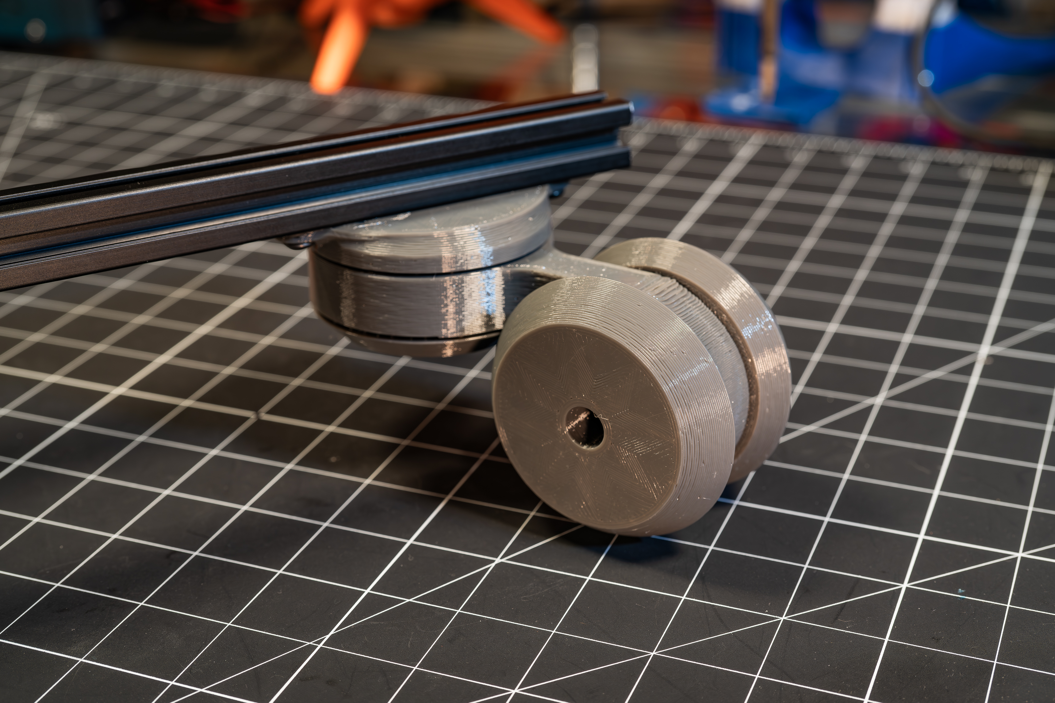
Playing around with an idea for some caster wheels.
Update - Load Testing to failure
Failed at a little over 600 Newtons! (~140lbf)
Build
I think the little video above pretty much covers the build process. The only part not shown is inserting the heat sets into the FrameMount and one of the wheels.
BOM
- Printed Parts
- FrameMount
- Hub
- Retainer
- Wheel (x2)
- COTS
- (2) M5 heat set - I used short ones
- (30) 9.5mm balls - I use this 3/8" slingshot ammo...kind of alot.
- (2) M5x10 Fastener - I used a couple BHCS
Just pop in the heat sets, toss in some balls, and tighten...sounds so easy in theory, doesn't it? :)
If either of the bearings feel too tight, you can add a washer in between the mating parts to free things up a bit. You could also probably just extrude the face in your slicer also. For the one shown above, I had no spacers on the main bearing and one washer between the wheels. It puts the wheels on the sloppy side, but that's kinda what I want (I'm hoping this will make it hold up to pet hair and the like a smidge longer ¯\_(ツ)_/¯)
Design
CAD files available on OnShape, here.
A caster wheel is essentially just two rotational axes, othogonal to each other and with a radial offset (and if you read on all the way through the Design Notes below, you'll see that I managed to overlook this last one initially...oops.)
To create these rotational axes, I decided to use my old favorite, bearing races integrated into the printed parts and fillin em with balls.
 |
 |
 |
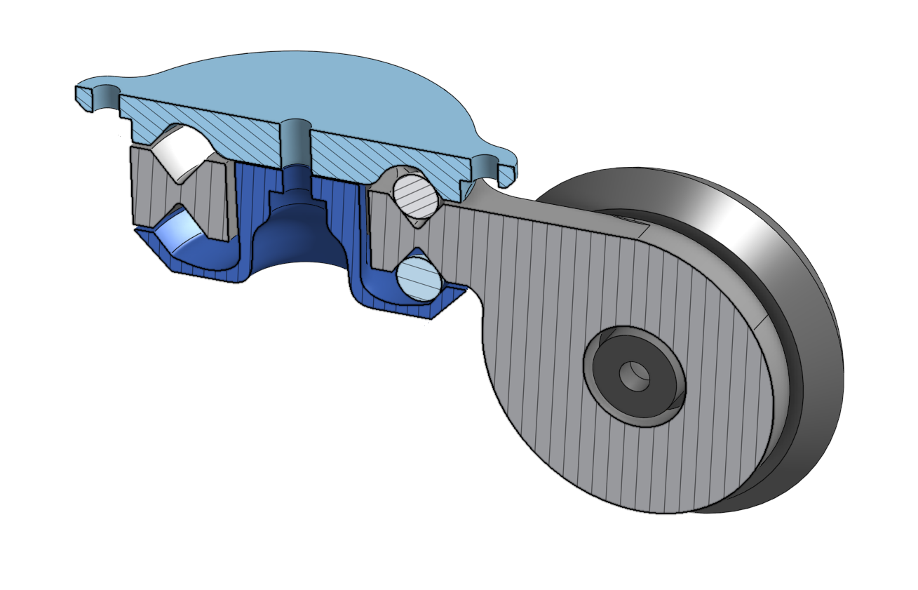
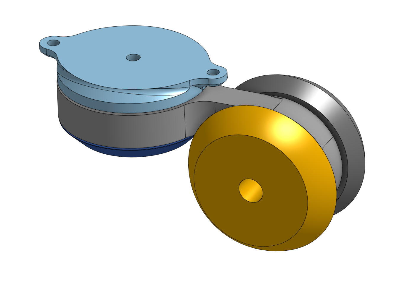
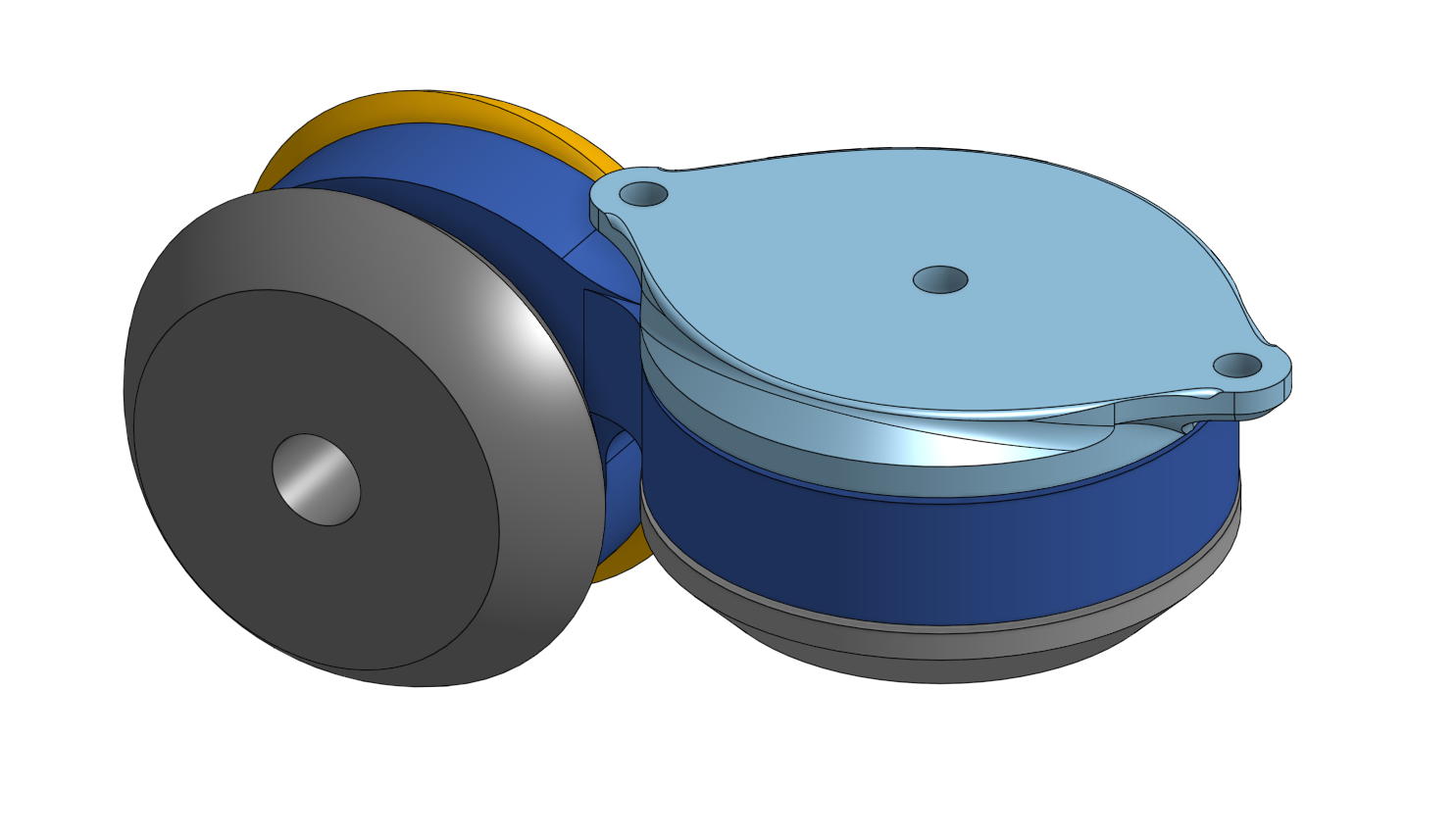
The light blue part in the image above is the FrameMount. It provides one of the main bearing races and is also the attachment point to the structure to be wheeled about.
The light grey part is the Hub. It houses the inner races for both the main bearing and wheel bearing. It's also the part that I suspect to be the one that fails under heavy load :)
The dark blue part, shown best in the image on the left, is the Retainer. It is the other outer race for the main bearing and also provides the preload for the bearing.
And the yellow and dark grey parts are the wheels. They are both the same Wheel part and in addition to being the wheels they, can you guess?...that's right, they're also bearing races, kinda repetitive, eh?
Although only one ball is shown in each race in the above, they should be fully filled to ensure proper load distribution.
The nominal design includes small (0.5mm) gaps between the Retainer and FrameMount, as well as between the wheels. This is to allow for developing a preload in the bearing as these surfaces are brought into contact. The thin-walled geometry of the Retainer is intended to act as a source of compliance, instead of using something like a spring washer or the like. I was too lazy to do the same for the wheels, and it shows in operation. However, in iterating on the design, I realized I actually kind of prefer these bearings to have a very low preload. This is mainly because I don't really care at all about the runout in these bearings (or at least so I believe today....we shall see), and I do want them to spin as freely as possible.
So I decided to just leave the gaps and such as is, and dial in the preload I want by inserting a washer or washers in this gap.
Design Notes
V1 - Epic fail
Well, isn't this embarrassing. In my excitement at the idea of just nesting integrated bearings to obtain a caster wheel (but also just kind of intrigued by the idea of using this concept for gimbals, trunions, etc.) I seem to have overlooked a very basic principle of caster wheels. An image of this model is shown below. Can you see the error of my ways? :)
No? It's ok, clearly I couldn't either. Yes? Well, where were you a week ago?
For a caster wheel to do its castering thing, it relies on the moment generated by the offset between the wheel/floor contact point and the axis of the main bearing. That way, when being pushed any direction where this moment is produced (any component of the push direction being normal to the rolling direction of the wheel) the main bearing rotates, aligning the wheel to the direction of the push.
In my love of symmetry, I just completely overlooked this until I assembled the thing and was dumbfounded by it's lack of desire to rotate.
Luckily, I did realize my error prior to just iterating on my oopsie. So, on to V2
V2
2024/01/12 - Design notes
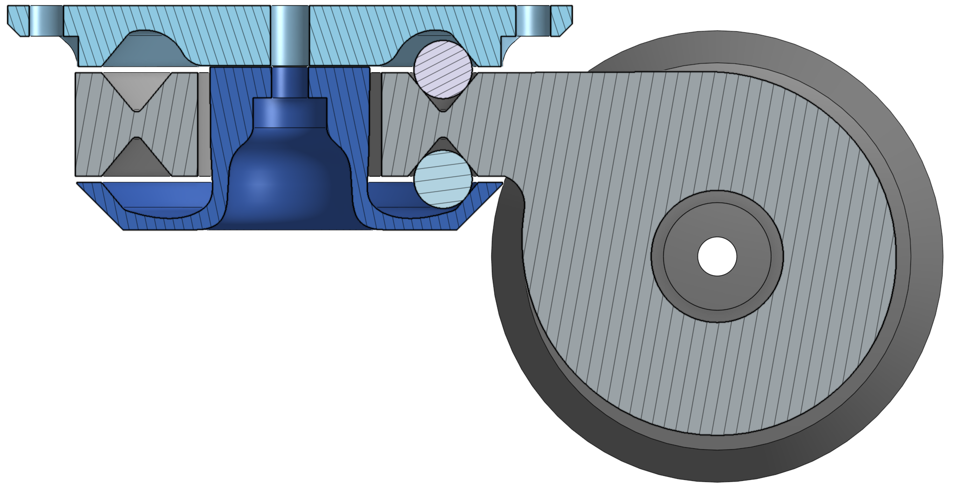
The below image shows the main bearing concept xsec (I haven't patterned the balls yet). The light blue part on top is the rigid attachment point that will go to the frame being wheeled about. The dark blue part will be what attaches to the wheel, and the grey piece is the retainer. The thin walls and contour of the retainer is intended to provide some compliance. There is a nominal gap of 1mm between the retainer and the frame mount. The frame mount will have an M5 heat set, and tightening this M5 will deform the compliant retainer, preloading the bearing. The plan is to fully close this 1mm gap, but as usual, 3d printed flexural elements can be difficult to predict/calculate, so I'm just going with an 'estimate and test it' approach.
I think I have the main bearing where I want it. I'm curious how this bearing config will feel. Given that it's getting late, I think I may just print this assembly overnight and see how I like it in the morning.
2024/01/13 - Design notes
I lied above. I was apparently more tired than I realized, and those parts didn't even make it to the slicer :)
So instead I went ahead and finished out the V2 design this morning. As you can see in the image below, I may have overcompensated a smidge with my offset. The extent of the offset was really more the result of liking the small(er) overall package size this offered. My assumption is that this connection structure between the main bearing and wheel bearing will be the failure point when overloaded, but I also wouldn't be surprised if the loads on the retainer are higher than I am expecting, letting it earn the award for weakest link...I suppose we shall see.
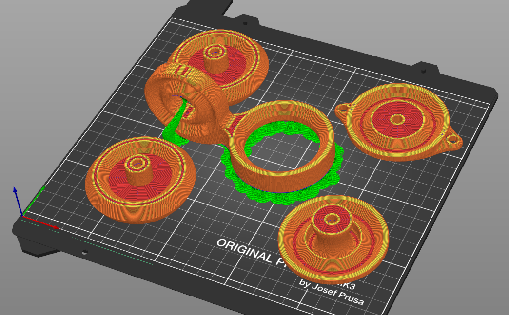
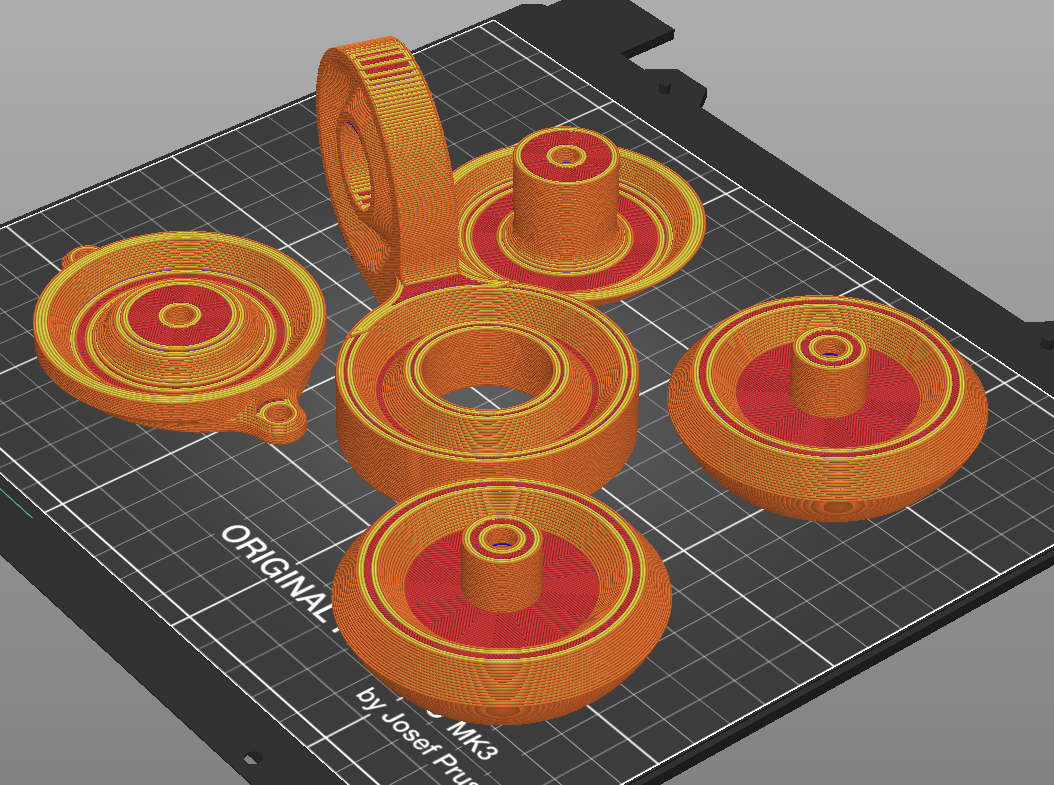
All of the parts fit comfortably on a single build mk3 build plate, and with my print settings that yields a print time of right about 6 hours. Total material consumed should be ~190 grams.
2024/01/13 - Build comments/takeaways
- Good lord was this thing a pain in the ass to assemble! The configuration of the main bearing allowed the balls to easily fall too far out of position to be self-aligned during preload...aka balls went f*&%ing everywhere :)
- The wheel bearing, however, was substantially easier and self-aligned quite well in repeated tests.
- The wheel bearing could use a better-defined preload. I inserted stacked washers in between the wheels to set the spacing, but ended up going with basically zero preload in the bearing. Although this makes the bearing pretty sloppy, I'm not sure I actually mind for this application. As long as it stays assembled and allows free rotation, I don't really care about runout. May go with an intentional zero preload design for V3.
- As usual, support structures suck :) Although not a significant problem to remove on this one, I really don't like having the decreased surface finish so close to the bearing race surface. Changing the geometry to get the outer diameter of the main bearing race is tangent to the flat on top of the wheel bearing (to remove the ring of supports shown in the above screen shot.
- IT CASTERS (I know this isn't actually a verb...but hey, it's the internet, I can make up whatever I want, right? :) ). Other than the assembly woes, it does indeed function as desired! No clue what a realistic load operating range it will be suited to, but at least it does it's base function.
V3
2024/01/14 - Design notes
There were two main issues from V2 that I want to address in V3, which I'm hoping will be the final rev for the time being.
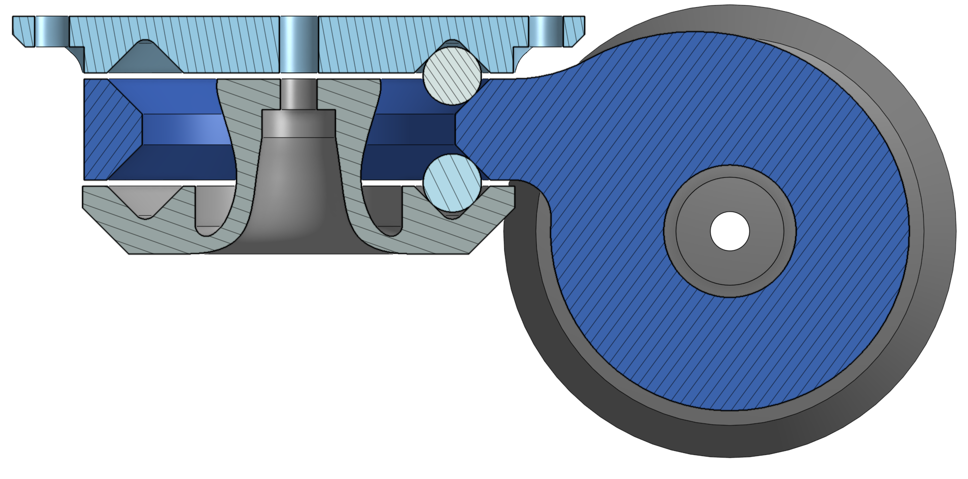
- The main issue with V2 was with the reality of assembly for the main bearing. Although it is full constrained when assembled, it was an absolute nightmare keeping the balls in their races while putting it together. Since the wheel bearing assembly was substantially easier to work with, I'm going to replicate that bearing configuration for the main bearing as well. The below cross section shows the revised bearing along side the V2 config. Essentially it moves the ball plane definition to the Hub, instead of in the FrameMount and Retainer.
- Also visible in the below cross sections, the wheel axis was moved down to make the outer diameter of the wheel race tangent to the top surface of the main bearing race
 |
 |
I think V3 seems good enough to call it for now on this bad boy! (at least until I actually install it on something and realize it's deficient is some yet-unknown way :) ).